Author:
Nathan Ruiz, Sales Application Engineer, Kikusui America, Inc.
Date
09/03/2022
 PDF
PDF

Low-Voltage Solution for Load Variation Testing
The use of semiconductors in devices has skyrocketed in past decades. This leads to a large growth in the demand for more semiconductor components and the need to develop new solutions to power each device. Compounded with this growth in the market is the drive for increased performance and efficiency for each new technology. The most used method to achieve both has been reducing the voltage semiconductors operate at. This has been a long-standing trend and shows no sign of stopping. The downward trend for operating voltage creates a challenge for new power supplies that need to be designed and tested at low voltages, sometimes down to 0 volts.
The issue arises when using an electronic load, such as the PLZ-5W, to perform load testing on low voltage power supplies. Most e-loads are designed using transistor technology which allows them to define a set load current. However, this also implies a minimum voltage for the e-load to start drawing any current. How does one then test a power supply with an output voltage lower than the operating voltage of the load unit? This is where introducing a bias power supply greatly improves compatibility.
Why Not Use the PLZ-5W at Low Voltages?
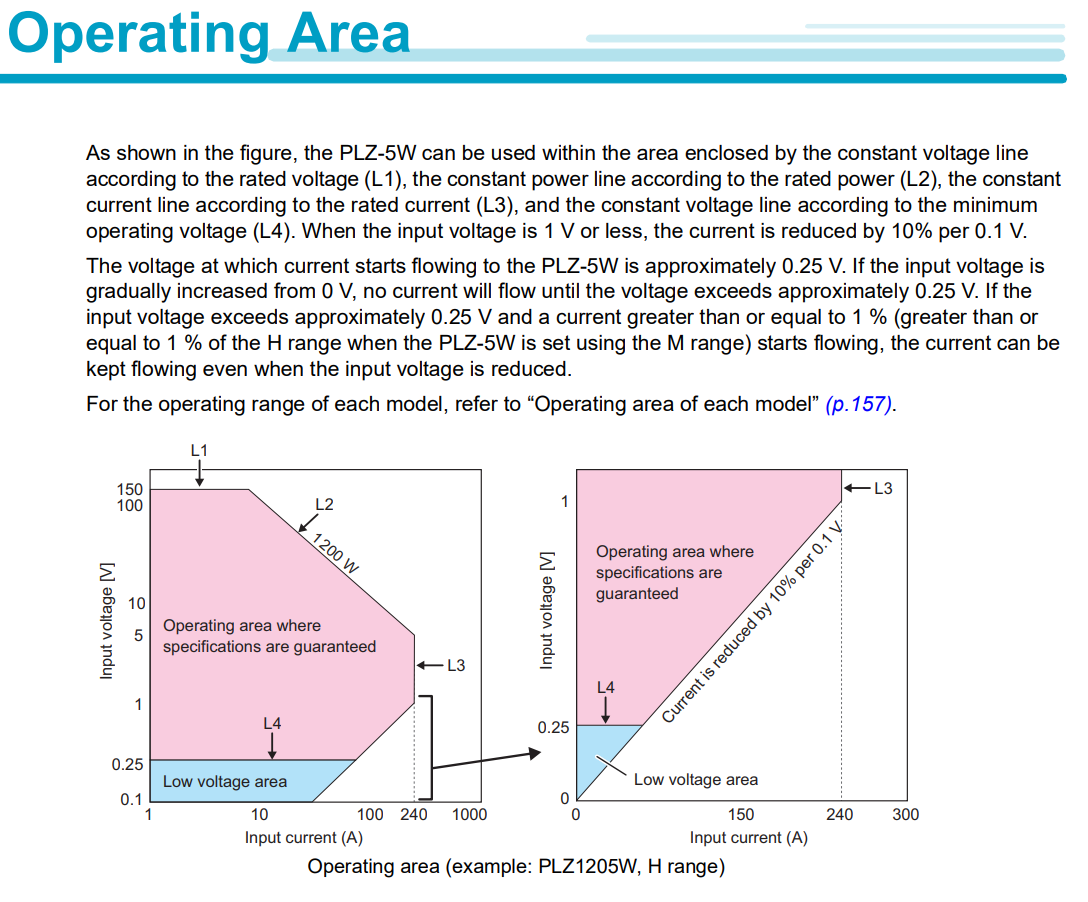
The PLZ-5W is the latest model of DC e-loads offered by Kikusui. This series used to be rated with a minimum operating voltage of 1V. However, this rating has been relaxed down to 0.25V recently, although with some restrictions. Like most e-loads, there will be a degrading of the maximum available load current if the voltage is below the rated 1V. There are more details found in Figure 1. For example, if the operating voltage is 0.25V, then the PLZ-5W used will need to be able to supply 4 times the desired current flow.
Using a Bias Power Supply
The main principle behind using a bias power supply is to boost the voltage drop across the e-load while keeping the power supply under test (DUT) set to a low voltage. This can be achieved by connecting each unit in series, as shown in Figure 2.

Figure 2: Simple block diagram using a bias power supply in series with an e-load and a power supply under test.The voltage drop that is applied on the e-load (Vload) will be the sum of the bias power supplies set voltage (Vbias) and the DUT’s test voltage (Vdut). With a large enough Vbias, the e-load can operate at full capacity while the DUT can be tested at 0V. This setup also works for testing batteries and supplies at negative voltages.
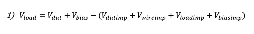
However, Figure 2 only provides a rough estimate of an actual setup. For more rigorous testing, a more detailed model is needed and worth keeping in mind. Figure 3 shows the same setup with blocks representing the internal impedances in each component. Using this model, the resulting voltage across the e-load is no longer a simple sum. Instead, it has extra impedances reducing the effectiveness. Equation 1 below describes this relationship.

Click image to enlarge
Figure 3: Block diagram using a bias power supply in series with an e-load and a power supply under test with internal impedances and wire impedance shown. Reducing the Effect of Internal Impedances
Assuming that these internal impedances are not negligible and are mostly inductive, the measured voltage across the low voltage supply under test (Vdut + Vdutimp) can increase while the current increases rapidly. This result can interfere with testing the DUT’s ability to supply low voltage. Thankfully, one can mitigate this effect by connecting an appropriately sized capacitor across the output terminals of the DUT. With a capacitor in place, a rapid increase in current can be sourced by both the DUT and the capacitor, thus reducing the voltage drop Vdutimp and keeping the measured voltage closer to the set value, Vdut.
This same logic for the DUT output can be applied to the bias power supply as well. If there is a large difference in the measured voltage of the bias supply (Vbias + Vbiasimp) and the set voltage, Vbias, connect a capacitor to the output terminal of the bias power supply.
Testing Fast Load Responses by Keeping a High Slew Rate
When performing load variation testing, one key aspect to test is the response of the DUT. New devices are getting faster, meaning that power supplies need to be tested with a fast change in current. For this purpose, it’s important to keep in mind the slew rate characteristics of the e-load used during testing. Almost all e-loads, such as the PLZ-5W from Kikusui, have a maximum rated slew rate that can only be achieved under certain conditions.
For the PLZ-5W series, the rated 60A/µs of slew rate was achieved using a change in set load current from 0% to 100% of the rated current output. For example, the PLZ1205W can only draw at 60A/µs when the current changes from 0A to 480A.
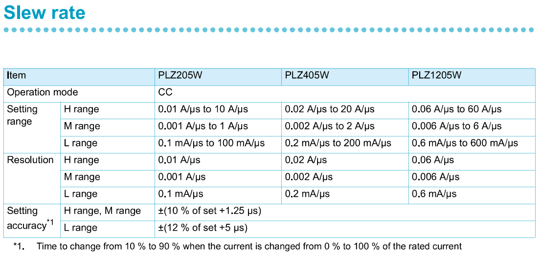
Depending on the e-load used, there can be an additional setting that affects the maximum slew rate, such as the load current range setting. The PLZ-5W has three range options for different levels of voltage output, which each range having a slower slew rate than the last. Please see Figure 4 for a list of all specified slew rates for the PLZ-5W series.
If the load current doesn’t vary from 0% to 100%, as is used to measure the maximum slew rate, then the maximum slew rate will vary differently for each range. Figure 5 shows more detail on this.
Click image to enlarge
Figure 4: Slew rate specifications for the PLZ-5W series. This is a snippet from the operation manual which can be seen here. https://kikusuiamerica.com/products-index/electronic-load/plz-5w-5wz/#section-5

Click image to enlarge
Figure 5: Slew rate for each load current range of the PLZ-5W series.
Setting the Bias Voltage
When connecting a DUT with this setup, there is still a choice in the voltage set on the bias power supply, Vbias. Ideally, this voltage should be low to reduce power draw. Also, a higher voltage might interfere with the ground isolation of the DUT. When it comes to testing for load responses and changing the load current quickly, there is also a restriction on the minimum operating voltage of the PLZ-5W. To keep a high slew rate, the operating voltage should be increased based on the equation in the red box of Figure 6.

Click image to enlarge
Figure 6: Operating voltage range and offer specifications for the PLZ-5W series.
As an example, let’s say the PLZ1205W is used for a fast response test at 120A, which is 50% of the rated current. For the range 0% to 50%, the PLZ1205W will have a maximum slew rate of around 60A/µs. Knowing that the minimum operating voltage for the PLZ1205W is 0.25V, the recommended minimum voltage drop to achieve 60A/µs in this example is around 4.75V.
Giving an Example
To conclude, here is an example scenario and steps to help select an e-load and a bias power supply. In this example, the DUT is rated for 0.7V (Vdut). It needs to be tested at a maximum of 100A (I) and responds to 50A/µs.
First, the voltage drop due to each impedance as described in Equation 1 should be deduced. For this example, let’s assume the wire impedance leads to a 5V (Vwireimp = 5V) and all other internal impedance are negligible.
Next is determining the e-load for this test. The best PLZ-5W e-load to fit this scenario would be the PLZ1205W since the current (100A) and power (70W) for this test matches the rated current (240A) and power (1200W) of this unit. Since the current is greater than 24A, the PLZ1205W will be operating in the H range. Given that and the fact that the current used is ~40% of the rated current, Figure 5 can be used to ensure that at least 50A/µs is possible.
To determine the bias power supply to use, the bias voltage (Vbias) will need to be calculated. Figure 6 describes the method to determine Vload. For this example, Vload will be 4V (0.25V + 75mV * 50). Equation 1 gives the bias voltage to be 8.3V or more. Thus, the bias power supply used needs to be rated for 8.3V, 100A, and 830W at least. For this scenario, the PWR1201L DC programmable power supply would be a good fit.
Therefore, to create a setup to test a supply at 0.7V and 100A for a response at 50A/µs, a PLZ1205W e-load can be connected in parallel with a PWR1201L bias power supply. This setup would not be possible without the bias power supply since the PLZ1205W would not have the voltage drop required to produce a fast enough load change.