Maximize Run Time in Automotive Battery Stacks Even as Cells Age
All Series-Connected Cells Need to Be Balanced
Large battery stacks consisting of series-connected, high energy density, high peak power Lithium polymer or Lithium-Iron Phosphate (LiFePO4) cells are commonplace in applications ranging from all-electric (EV or BEV) and hybrid gas/electric vehicles (HEVs and plug-in hybrid electric vehicles or PHEVs) to energy storage systems (ESS). The electric vehicle market in particular is forecast to create tremendous demand for large arrays of series/parallel connected battery cells. The 2016 global PHEV sales were 775,000 units [Source: EVvolumes.com], with a forecast of 1,130,000 units for 2017. Despite the growing demand for high capacity cells, battery prices have remained quite high and represent the highest priced component in an EV or PHEV with prices typically in the $10,000 range for batteries capable of a few 100s of kilometers of driving range. The high cost may be mitigated by the use of low cost/refurbished cells, but such cells will also have a greater capacity mismatch, which in turn reduces the usable run time, or drivable distance on a single charge. Even the higher cost, higher quality cells will age and mismatch with repeated use. Increasing stack capacity with mismatched cells can be done in two ways: either by starting with bigger batteries, which is not very cost effective, or by using active balancing, a new technique to recover battery capacity in the pack which is quickly gaining momentum.
All Series-Connected Cells Need to Be Balanced
The cells in a battery stack are balanced when every cell in the stack possesses the same state of charge (SoC). SoC refers to the current remaining capacity of an individual cell relative to its maximum capacity as the cell charges and discharges. For example, a 10A-hr cell with 5A-hrs of remaining capacity has a 50% SoC. All battery cells must be kept within a SoC range to avoid damage or lifetime degradation. The allowable SoC min and max levels vary from application to application. In applications where battery run time is of primary importance, all cells may operate between a min SoC of 20% and a max of 100% (or a fully charged state). Applications that demand the longest battery lifetime may constrain the SoC range from 30% min to 70% max. These are typical SoC limits found in electric vehicles and grid storage systems, which utilize very large and expensive batteries with an extremely high replacement cost. The primary role of the battery management system (BMS) is to carefully monitor all cells in the stack and ensure that noneof the cells are charged or discharged beyond the min and max SoC limits of the application.
With a series/parallel array of cells, it is generally safe to assume the cells connected in parallel will auto-balance with respect to each other. That is, over time, the state of charge will automatically equalize between parallel connected cells as long as a conducting path exists between the cell terminals. It is also safe to assume that the state of charge for cells connected in series will tend to diverge over time due to a number of factors. Gradual SoC changes may occur due to temperature gradients throughout the pack or differences in impedance, self-discharge rates or loading cell to cell. Although the battery pack charging and discharging currents tend to dwarf these cell-to-cell variations, the accumulated mismatch will grow unabated unless the cells are periodically balanced. Compensating for gradual changes in SoC from cell to cell is the most basic reason for balancing series connected batteries. Typically, a passive or dissipative balancing scheme is adequate to re-balance SoC in a stack of cells with closely matched capacities.
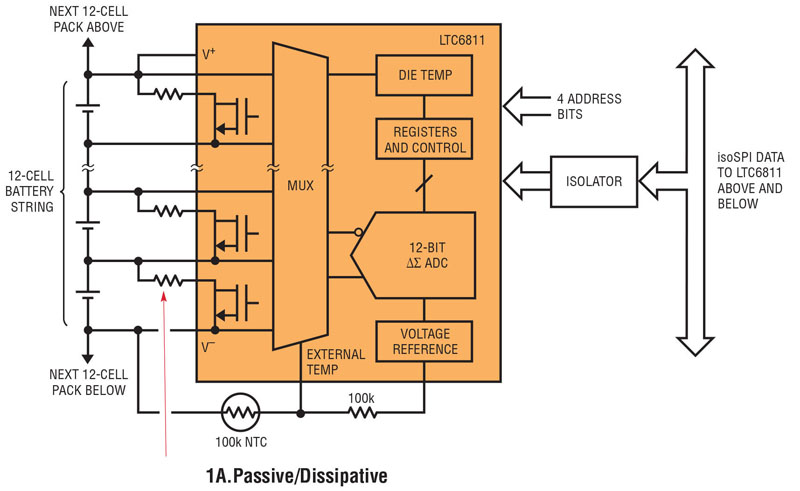
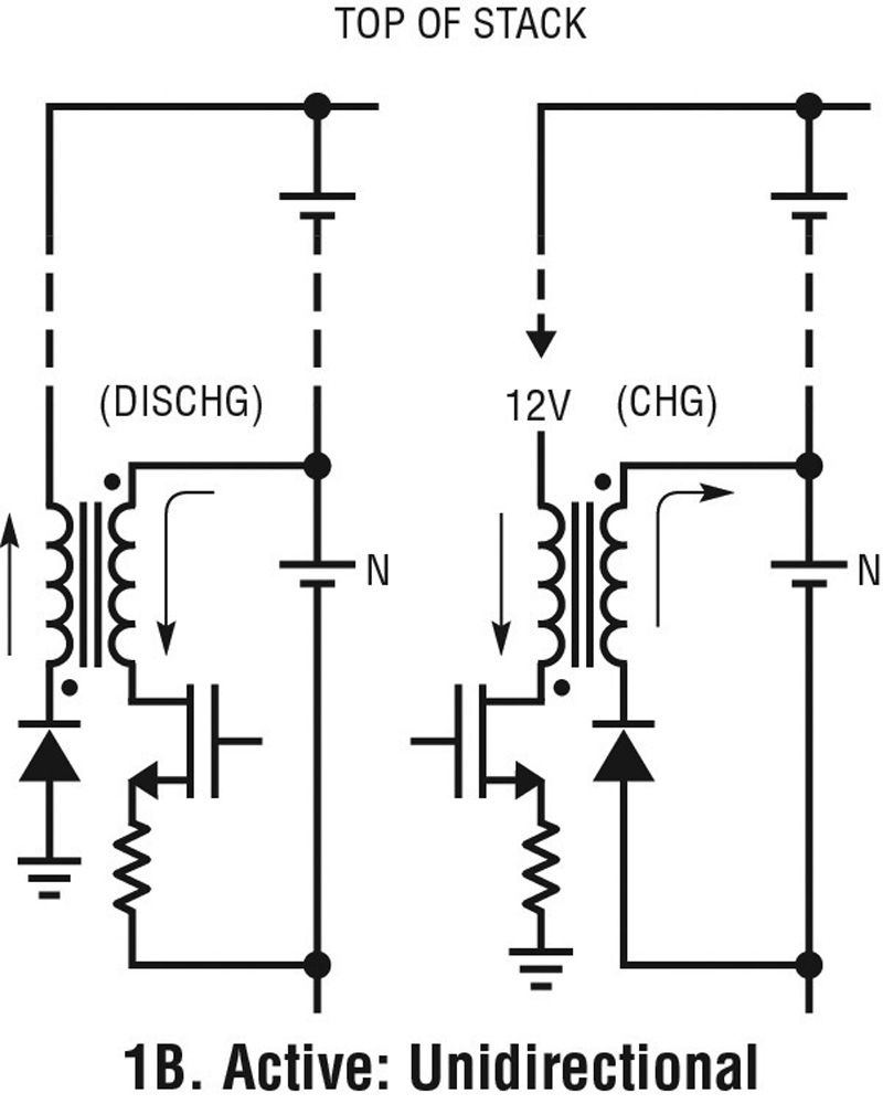
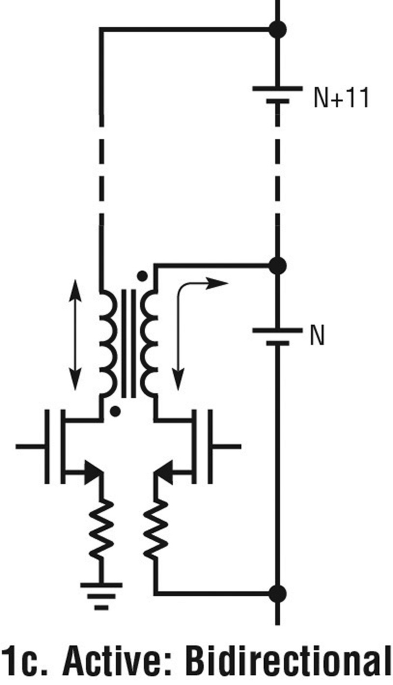
As illustrated in Figure 1a, passive balancing is simple and inexpensive. However, passive balancing is also very slow, generates unwanted heat inside the battery pack and balances by reducing the remaining capacity in all cells to match the lowest SoC cell in the stack. Passive balancing also lacks the ability to effectively address SoC errors due to another common occurrence, capacity mismatch. All cells lose capacity as they age and they tend to do so at different rates for reasons similar to those listed above. Since the stack current flows into and out of all series cells equally, the usable capacity of the stack is determined by the lowest capacity cell in the stack. Only active balancing methods such as those shown in Figures 1b and 1c can redistribute charge throughout the stack and compensate for lost capacity due to mismatch from cell to cell.
Click image to enlarge
Click image to enlarge
Click image to enlarge
Figure 1. Typical Cell Balancing Topologies
Cell-to-Cell Mismatch Can Dramatically Reduce Run Time
Cell-to-cell mismatch in either capacity or SoC may severely reduce the usable battery stack capacity unless the cells are balanced. Maximizing stack capacity requires that the cells are balanced both during stack charging as well as stack discharging.
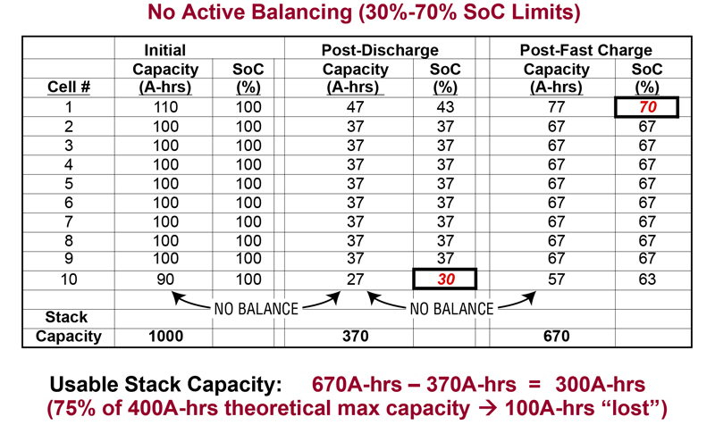
In the example shown in Figure 2, a 10-cell series stack comprised of (nominal) 100A-hr cells with a +/- 10% capacity error from the minimum capacity cell to the maximum is charged and discharged until predetermined SoC limits are reached. If SoC levels are constrained to between 30% and 70% and no balancing is performed, the usable stack capacity is reduced by 25% after a complete charge/discharge cycle relative to the theoretical usable capacity of the cells. Passive balancing could theoretically equalize each cell’s SoC during the stack charging phase, but could do nothing to prevent cell 10 from reaching its 30% SoC level before the others during discharge. Even with passive balancing during stack charging, significant capacity is lost (not usable) during stack discharge. Only an active balancing solution can achieve capacity recovery by redistributing charge from high SoC cells to low SoC cells during stack discharging.
Click image to enlarge
Figure 2. Stack Capacity Loss Example Due to Cell-to-Cell Mismatch
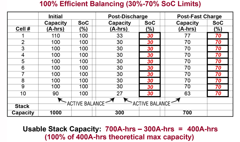
Figure 3 illustrates how the use of ideal active balancing enables 100% recovery of the lost capacity due to cell-to-cell mismatch. During steady state use when the stack is discharging from its 70% SoC “fully” recharged state, stored charge must in effect be taken from cell 1 (the highest capacity cell) and transferred to cell 10 (the lowest capacity cell) – otherwise cell 10 reaches its 30% minimum SoC point before the rest of the cells, and the stack discharging must stop to prevent further lifetime degradation. Similarly, charge must be removed from cell 10 and redistributed to cell 1 during the charging phase – otherwise cell 10 reaches its 70% upper SoC limit first and the charging cycle must stop. At some point over the operating life of a battery stack, variations in cell aging will inevitably create cell-to-cell capacity mismatch. Only an active balancing solution can achieve capacity recovery by redistributing charge from high SoC cells to low SoC cells as needed. Achieving maximum battery stack capacity over the life of the battery stack requires an active balancing solution to efficiently charge and discharge individual cells to maintain SoC balance throughout the stack.
Click image to enlarge
Figure 3. Capacity Recovery Due to Ideal Active Balancing
High Efficiency Bi-Directional Balancing Provides Highest Capacity Recovery
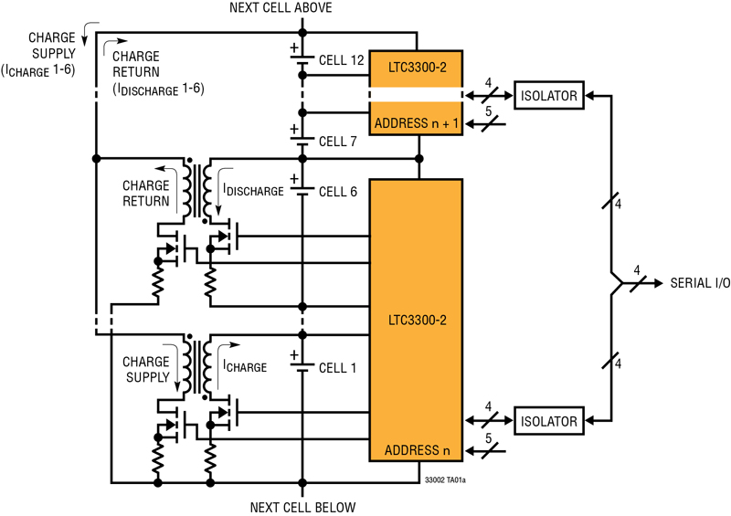
The LTC3300-2 (see Figure 4) is a new product designed specifically to address the need for high performance active balancing. The LTC3300-2 is a high efficiency, bi-directional active balance control IC that is a key piece of a high performance BMS system. Each IC can simultaneously balance up to 6 Li-Ion or LiFePO4 cells connected in series.
Click image to enlarge
Figure 4. LTC3300-2 High Efficiency Bi-Directional Multicell Active Balancer
SoC balance is achieved by redistributing charge between a selected cell and a sub-stack of up to 12 or more adjacent cells. The balancing decisions and balancing algorithms must be handled by a separate monitoring device and system processor that controls the LTC3300-2. Charge is redistributed from a selected cell to a group of 12 or more neighboring cells in order to discharge the cell. Similarly, charge is transferred to a selected cell from a group of 12 or more neighbor cells in order to charge the cell. All balancers may operate simultaneously, in either direction, to minimize stack balancing time. The LTC3300-2 has an SPI bus compatible serial port. Devices can be connected in parallel, using digital isolators. Multiple devices are uniquely identified by a part address determined by the A0 to A4 pins. On the LTC3300-2, four pins comprise the serial interface: CSBI, SCKI, SDI and SDO. The SDO and SDI pins may be tie together, if desired, to form a single bidirectional port. Five address pins (A0 to A4) set the part address. All serial communication related pins are voltage mode with voltage levels referenced to the VREG and V– supplies.
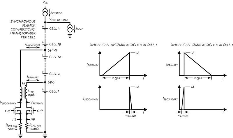
Each balancer in the LTC3300-2 uses a non-isolated boundary mode synchronous flyback power stage to achieve high efficiency charging and discharging of each individual cell. Each of the six balancers requires its own transformer. The primary side of each transformer is connected across the cell to be balanced, and the secondary side is connected across 12 or more adjacent cells, including the cell to be balanced. The number of cells on the secondary side is limited only by the breakdown voltage of the external components. Cell charge and discharge currents are programmed by external sense resistors to values as high as 10+ amps with corresponding scaling of the external switches and transformers. High efficiency is achieved through synchronous operation and the proper choice of components. Individual balancers are enabled via the BMS system processor and they will remain enabled until the BMS commands balancing to stop or a fault condition is detected.
Balancer Efficiency Matters!
One of the biggest enemies faced by a battery pack is heat. High ambient temperatures rapidly degrade battery lifetime and performance. Unfortunately, in high current battery systems, the balancing currents must also be high in order to extend run times or to achieve fast charging of the pack. Poor balancer efficiency results in unwanted heat inside the battery system, and must be addressed by reducing the number of balancers that can run at a given time or through expensive thermal mitigation methods. As shown in Figure 5, the LTC3300-2 achieves >90% efficiency in both the charging and discharging directions, which allows the balance current to be more than doubled relative to an 80% efficient solution with equal balancer power dissipation. Furthermore, higher balancer efficiency produces more effective charge redistribution, which in turn produces more effective capacity recovery and faster charging.
Click image to enlarge
Figure 5. LTC3300-2 Power Stage Performance
Conclusion
While new applications such electric and PHEVs that are growing rapidly, consumer expectations for long operating life and reliable operation remain unchanged. Automobiles, whether they be battery or gasoline powered, are expected to last for over 5 years without any perceptible degradation in performance. In the case of an EV or PHEV, performance equates to drivable range under battery power. EV and PHEV suppliers must provide not only high battery performance, but also a multi-year warranty, guaranteeing a minimum range to remain competitive. As the number and age of electric vehicles continues to grow, irregular cell aging within the battery pack is emerging as a chronic problem and primary source of run time reduction. The operating time of a series-connected battery is always limited by the lowest capacity cell in the stack. It only takes one weak cell to compromise the whole battery. For the vehicle suppliers, replacing or refurbishing a battery under warranty due to insufficient range is a very expensive proposition. Preventing such a costly event can be accomplished by using larger, more expensive batteries for each and every cell, or by adopting a high performance active balancer such as the LTC3300-2 to compensate for cell-to-cell capacity mismatch due to non-uniform aging of the cells. With the LTC3300-2, a severely mismatched stack of cells has nearly the same run time as a perfectly matched stack of cells with the same average cell capacity.