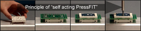
Self acting PressFIT module simplifies assembly - maintains reliability
Customers of power electronics increasingly require new, easy connection and mounting technologies. PressFIT technology creates the possibility of solderless mounting combined with an improved reliability. To continue this approach, a new module platform based on PressFIT technology has been developed which furthermore offers an extremely fast and robust mounting concept to improve inverter manufacturing, reliability and design. Special emphasis has been put on mechanical robustness. Avoiding the risk of DCB cracks resulting from controllable forces originating from the module design, was one of the main approaches. To demonstrate the robustness, comprehensive mechanical tests were carried out.
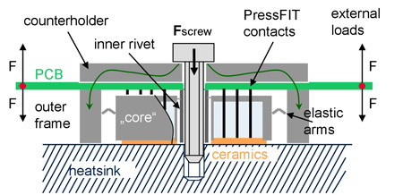
Regarding current module designs, there are three main improvement areas, which have to be combined into one solution: So the approach is, to get a module which is suitable for a single step mounting process with a high mechanical robustness, in combination with a robust contact system. The Smart module is suitable for a single step mounting procedure by the use of PressFIT contacts, hence the name "self acting PressFIT". This means that the fixation at the heatsink, the electrical contact and the PCB fixation is done in just one very fast process step, simply by tightening a screw. A counterholder transfers the force from the screw to the PCB and pushes the contact pins into the dedicated holes. At the end, this pressure part rests onto the module and presses this to heatsink for a good thermal contact. Furthermore the PCB is fixed between the module frame and the counterholder after the mounting process, therefore no additional fixing points for the board are necessary around the module.
Further information: www.infineon.com/smart This Self acting PressFIT assembly is presented in the full Smart family. The family consists out of three packages, dedicated to the different power ranges. The following tests are carried out with the Smart1 module, but can be also roughly assigned for the Smart2 and Smart3, because of the similar mechanical concept. The mechanical design is benchmark regarding robustness. This is realized by a duplex frame, which prevents the ceramic substrate from all screw forces and also from other external loads. It consists out of an inner module core with the ceramic substrate and an outer decoupled parts frame. The screw force is only applied on the outer frame. The inner part has a vertical degree of freedom. Those two parts are connected with elastic elements which pushes the inner part to the heatsink. Also the PressFIT pins, which are directly distributed on the substrate, push onto the substrate.
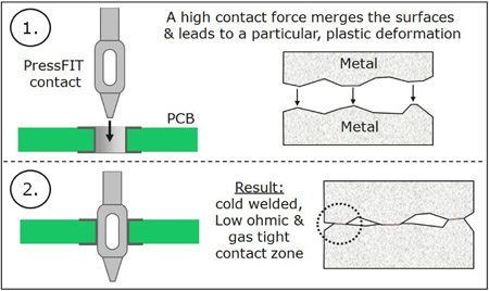
To enable the single step mounting process, a solderless connection technology is required. Within the Smart modules, the well proven PressFIT contacts are used. The reliability of a PressFIT contact is based on the gas tight contact zone, which is very robust against climatic influences and corrosive environments due to the particular plastic deformation in the local contact point which generates a cold welded connection. This results in very low FIT rates, which are approximately one decade below solder connections. So PressFIT should be the connection method with the highest potential for the future.
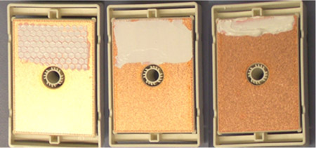
A trend in the market of low power semiconductor modules is to build the modules without the classic baseplate. This means, the module base is designed as the ceramic substrate, where the high power dies are bonded. In contrast to the smart concept, existing designs suffer the common risk of ceramic cracks due to high resulting pretensioning force of a screw. This results from the fact, that the force is applied directly onto the housing as can be seen. A ceramic crack leads to a safety relevant isolation failure, meaning the module has to be scrapped. The thermal grease, which is state of the art necessary for a good thermal interface between power module and heatsink, increases the risk of cracks due to its viscosity and velocity proportional absorbability.
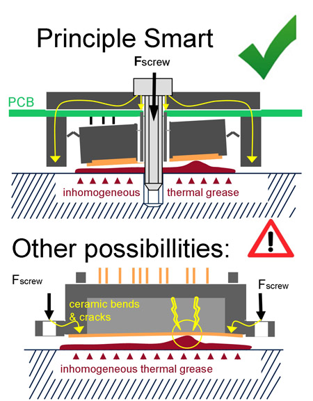
Unfortunately and especially if the thermal grease is applied by hand, there are some unavoidable fluctuations regarding the thickness of the grease. For the thermal behaviour of the module later on, these fluctuations are not objectionable, but due to the viscosity and velocity related damping of the grease material, they could be fatal for the ceramics and the isolation capability of the module. This comes from the inhomogeneous mechanical support and the resulting high, local bending stress which can lead to a crack. This risk becomes greater, the higher the mounting speed due to the speed of turning of the screw during assembly. To ensure the functionality of the Smart principle, some simple tests have been carried out, where the application of the thermal grease has been purposely falsely applied.
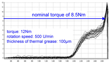
The request of modern manufacturing is to tighten screws as fast as possible. But as can be seen, a fastening machine is not able to stop exactly at a torque limit at that speed. It has an overshoot effect due to the inertia of the rotating masses. A common corrective action is to use a two step procedure, where the speed is reduced in the second one to values of 100U/min and below. A Smart module is suitable for a real one-step-mounting procedure with a rotation speed of 500U/min, due to its robust and force-absorbing design. Within the torque overload tests, thermal grease with a thickness of 100μm was applied. The Electrolube HTC material was chosen, because it has a very high viscosity, which is more critical for the crack sensitive ceramics. The overload torque was adjusted to a maximum of 12Nm (Figure 6), which is corresponding to a torque of 9Nm at a friction value of 0.10. All modules have been inspected and measured due to their isolation capability before and after the test: That means there is no DCB crack occurred and also the rest of the device was completely damage-free.
Many tests on the mechanical robustness and behaviour of the Smart1 module have been performed. All show that the Smart principle is a realized approach to cover all of today's main improvement areas in one power module: A solderless, robust single step mounting concept, combined with a reliable and universal contact system. Certainly, the Smart family will be extended to higher power ranges, with the same features and the same robustness. www.infineon.com


