Maximum Efficiency for Inverters
TDK has joined forces with Infineon Technologies to develop a design for xEV inverters that achieves a very high efficiency of over 98 percent over a power range of 10 kW to 150 kW. This success has been achieved by matching of the Infineon IGBT module and the EPCOS and TDK passive components.
The new Infineon HybridPACK Drive IGBT module is characterized by its compact design and high efficiency – essential criteria for e-mobility applications. The FS820R08A6P2B model is designed for a current of up to 820 A and a blocking voltage of 750 V and features a pin-fin heatsink for the coolant. These modules enable the realization of drives with output powers of up to 150 kW. The FS660R08A6P2FB with a flat baseplate can be used as an alternative, if less power is required. This IGBT module offers identical electrical behavior, but is designed for a maximum current of 660 A. The HybridPACK Drive family concept enables excellent scaling for a variety of power classes for both xEV and industrial applications.
Different module frames are already available in the product series and include those for weld contacting of load terminals (FS820R08A6P2) and frames with long motor terminals (FS820R08A6P2LB) for simple implementation of current sensors.
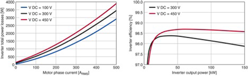
All modules of the R08A6P2 series are based on the latest generation of EDT2-IGBT chips from Infineon, designed for barrier-layer temperatures of up to 175 °C in the switching mode. The rugged chipset is resistant to short circuits and, even under the harshest environmental conditions, offers a very high level of reliability. Under realistic conditions of use, the R08A6P2 series achieves an efficiency of up to 98 percent (Figure 1). The module is optimized for switching frequencies in the range from 6 kHz to 10 kHz.
Click image to enlarge
Figure 1: Measured converter losses using the evaluation kit at a switching frequency of 8 kHz. The efficiency in the power range of 10 kW to 150 kW exceeds 98 percent (450 V operating voltage, cos φ=0.85). This results in improved ranges for plug-in and hybrid electric vehicles.
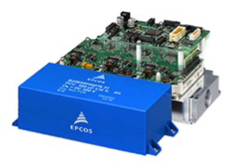
Thanks to the wide spacing between the connections, excellent insulation and minimal leakage currents are achieved, which means that the module is also suitable for high voltages, as is intended in future. Figure 2 shows a complete inverter, consisting of HybridPACK module with cooling plate, controller and driver board, as well as the EPCOS PCC capacitor for the DC link.
Click image to enlarge
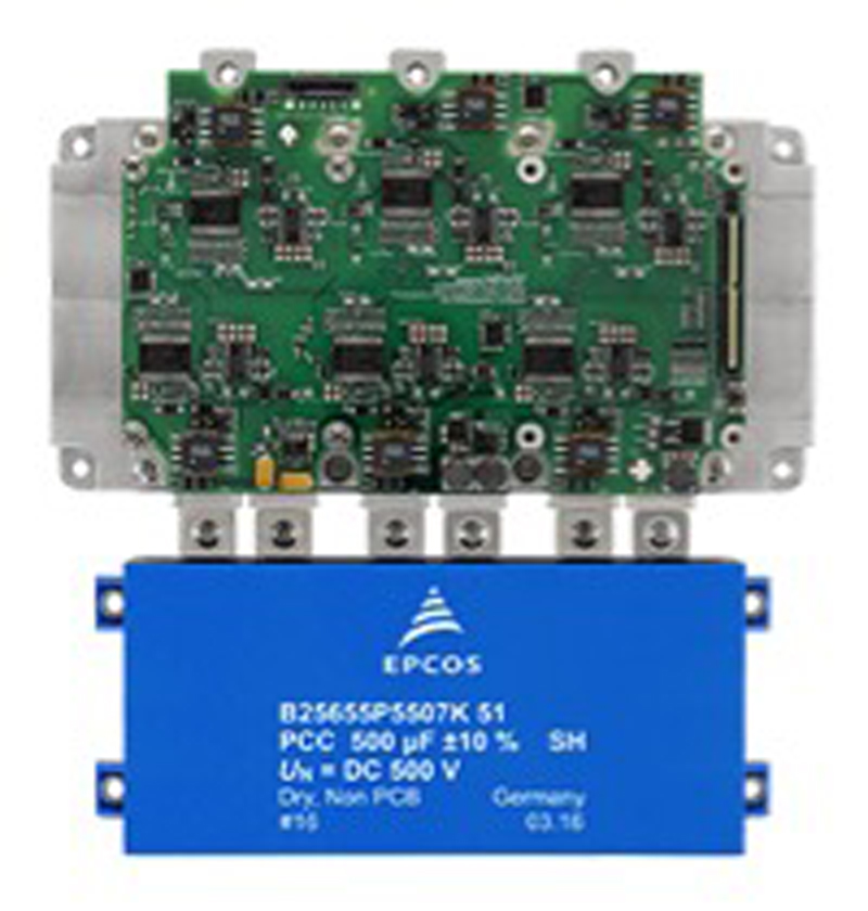
Figure 2: Complete motor inverter for a power output of up to 150 kW. The most important passive component is the EPCOS PCC as DC link capacitor. The complete design is available as an evaluation kit.
Compact solutions for the DC link
For this design, two EPCOS PCC capacitors come into consideration, which are also available for other HybridPACK modules. The B25655P5507K051 type features a stacked winding design, is designed for 500 V DC and, with a capacitance of 500 µF, can withstand continuous currents of up to 160 A. The great advantage of the stacked winding technology is its high volume fill-factor of nearly 1. The dimensions are 154 mm x 72 mm x 50 mm.
The second type (B25655P5407K1512) is based on the low-cost flat winding design and, due to its somewhat lower volume fill-factor, offers a capacitance of 400 µF for continuous currents of up to 140 A within the same dimensions. During design-in it is essential to ensure that the DC link capacitor is sufficiently cooled under maximum current load.
Low ESL and ESR values of the DC link capacitors are critical for a successful inverter design. Only with sufficiently low ESL values, is it possible to eliminate, or at least minimize, voltage peaks and oscillations when switching the IGBTs. The listed PCCs feature an ESL of just 15 nH. Their ESR values, responsible for the losses, are only 0.5 mΩ or 0.7 mΩ, respectively. These low values are achieved thanks to a large busbar with six terminals that are matched perfectly with those of the HybridPACK module (Figure 3). With modified busbar designs, values of less than 10 nH and less than 0.5 mΩ will be achieved in future.
Click image to enlarge
Figure 3: The busbar of the EPCOS PCCs has six large terminals and ensures that the ESL and ESR are minimized.
The production lines of the capacitors mentioned above comply with the requirements for automotive products, in order to achieve the greatest reliability. One particularly important factor here is the welding of the internal busbar, as its quality essentially decides the current-carrying capacity and the power loss. Apart from their high reliability, the EPCOS PCCs also offer excellent EMC performance, ensuring excellent noise suppression in the FM band around 100 MHz.
Galvanic isolation – an essential feature in automotive electronics
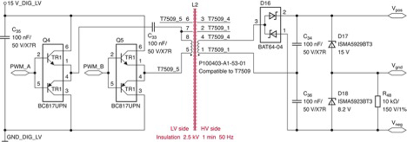
The driver board has the task of supplying three high-side and three low-side IGBTs with the necessary switching signals at their gates. It is essential to ensure sufficient galvanic isolation between the driver circuit and the IGBTs to prevent dielectric breakdown of the supply voltage to the driver board in the event of a fault. The crucial component for this purpose is the gate driver transformer. Figure 4 shows the circuit used for supplying the insulated IGBT drivers.
Click image to enlarge
Figure 4: The task of the gate driver transformer is to ensure galvanic isolation between the high-voltage and low-voltage sides.
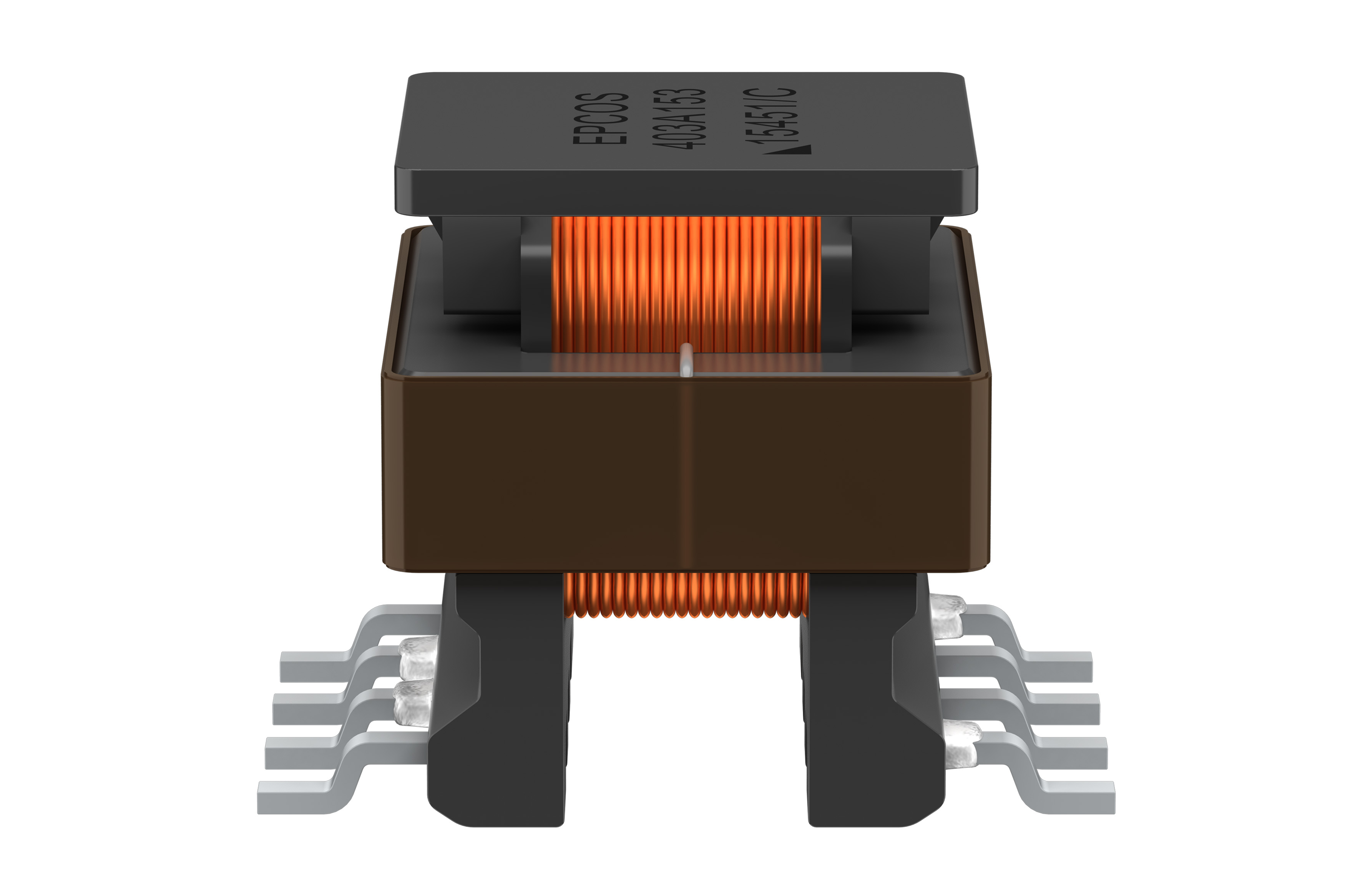
This reference design uses six B78307A2276A003 (P100403) EPCOS gate drive transformers. These ensure the necessary high insulation voltage of 2.5 kV (1 minute, 50 Hz). Their turns ratio is 1:1.08 and the inductance is 100 µH. Despite the high dielectric strength, the dimensions of the transformer are only 11.7 mm x 13.5 mm x 11.35 mm. The leakage current path between primary and secondary side is 6 mm, making it suitable for converters with a continuous operating voltage of 500 V.
Interference-free logic
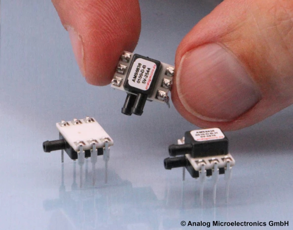
The controller board assumes the control of the entire inverter. Its heart is an Infineon 32-bit TC277 microcontroller from the AURIX automotive series. To ensure that the logic operates faultlessly, TDK ACT45B-101-2P-TL003 CAN-bus common-mode chokes are designed into the interfaces. At a frequency of 10 MHz these chokes exhibit a common-mode impedance of 5.8 kΩ, thereby ensuring interference-free data traffic. The chokes, which are qualified according to AEC-Q200, have dimensions of just 4.5 mm x 3.2 mm x 2.8 mm, making them among the smallest of their type in the world. TDK MMZ1608R600AT chip beads provide additional noise suppression in the signal cables.