Author:
Cathal Sheehan, Senior Technical Magnetics Marketing Manager at Bourns
Date
03/02/2023
 PDF
PDF

Click image to enlarge
Figure 1: As more renewable energy sources have been added to the grid, it has been become largely de-centralized where power comes from a variety of local sources
Today’s smart energy grids must be able to access real-time data collection through sophisticated communication, monitoring and control capabilities giving operators the ability to manage increasingly decentralized power generation and remedy any outage situations. Adding renewables and energy storage to the grid and meeting strict emissions goals exacerbates the challenges in meeting infrastructure design requirements. This is driving the development of reliable, efficient and cost-effective new power line component solutions. In particular, transformers have advanced as key components that help developers meet the narrowband design requirements in a rapidly increasing line of telecommunication systems that are part of next generation energy grids.
This article outlines some of the major changes in power distribution grid structures. To meet changing grid needs, the quality, faster service and infrastructure cost-saving benefits of incorporating Power Line Communication (PLC) technology are summarized. Specifically in meeting narrowband PLC-based system requirements, a straightforward galvanic isolation design method using advanced transformer features for a line coupling circuit is provided.
Power Grid Evolution
Power grids have evolved from using centralized power from fossil fuel-based plants that delivered power to customers through a large network of power lines.
And the addition of renewable energy sources has meant that other changes to the grid infrastructure needed to be made. For example, because of the intermittent nature of wind and solar, their power generation can change rapidly. This can lead to a potentially unbalanced power supply condition as generation must equal demand. When grid operations are unbalanced for too long, a blackout situation can occur. That’s why a more intelligent and robust ‘smart grid’ system has been developed, and where PLC communication in a smart grid system provides an advantage in that it can quickly detect a localized power outage.
Tapping Into PLC Technology Benefits
As previously stated, the new smart grid infrastructure relies on reliable, efficient communication technologies that provide the ability to transfer huge amounts of data. A significant benefit of PLC technology is that it utilizes existing power line infrastructure to seamlessly transfer information. A plus for those who design equipment for the smart grid is that PLC technology is already in use in existing systems so it has been proven in these types of applications. PLC technology is also liked by grid operators because it doesn’t require their equipment to share the communication channel with other systems, so it helps to reduce bandwidth variations.
Smart grids communication is accomplished by either wireless or wired methods. In existing infrastructure as it is used on power lines, wired communication offers data security and cost-effective advantages. There are no bandwidth variation issues with wired PLC technology, and PLC signals do not get obstructed by mountains or tall buildings. The main challenges for PLC technology are related to signal attenuation and noise. However, careful design can help to minimize the disturbance these issues potentially cause.
Conversely, although wireless communication can be installed quickly, it comes with cost, security, coverage area, and latency concerns that limited its deployment in smart grid applications. The consensus is that wired PLC is seen as a much more appealing option due to its lower cost and high capacity.
Designing Communication Isolation in PLC Systems
Power systems and communication systems operate at two different extremes. Power systems run at very low frequencies and at very high power. Communication systems operate at high frequencies and at low power. PLC circuits must be well-designed to handle these extremes and one key part of the PLC circuit is the line coupling circuit. The coupling circuit has two primary functions - isolation and coupling. Isolation is required to block mains high voltage from the low voltage modem circuit, and to also provide a path for the communication signal to pass via the AC mains line.
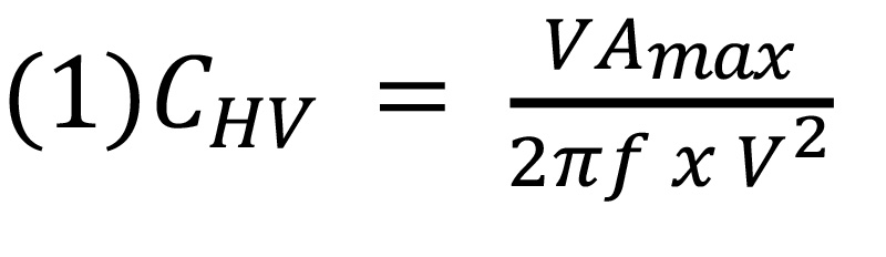
For a coupling operation to the mains, a high pass filter is necessary to filter out mains voltage and its associated harmonics. A high-voltage capacitor is placed before the transformer to accomplish this. The capacitor value can be calculated by using equation (1) where VAmax is the maximum reactive power, f the mains frequency and V the mains voltage.
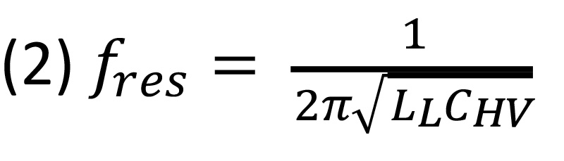
To provide galvanic isolation between its primary and secondary, a transformer is used. The high voltage capacitor in conjunction with the leakage inductance of the coupling transformer creates a series resonant coupling circuit. This series resonant circuit forms a second order band pass filter. The center frequency is calculated using Equation 2 where L refers to the series leakage inductance and C refers to the series capacitance.
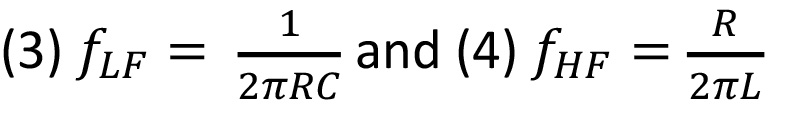
The frequency bandwidth is determined by low frequency and high frequency -3dB cut-off points. To measure these points, the respective formulas are given in Equation 3 and Equation 4 where R refers to the terminating resistance.
Click image to enlarge
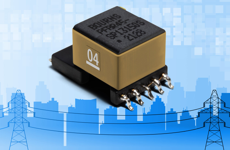
Figure 2: Bourns designed a new series of transformers for Narrowband PLC (NB-PLC) technology that help facilitate AC mains signal and PLC signal separation. The Bourns PFB Series transformers have been qualified with the ST Microelectronics ST8500 programmable PLC modem SoC and STLD1 Line Driver
In addition, designs must typically comply with the European CENELEC EN50065-1 standard, which defines maximum signal levels as well as permissible carrier frequency bands. It is also essential to match the modem impedance with the power line impedance. It is not frequently possible to change modem impedance so a transformer’s impedance matching characteristic is a good design resource. Since a transformer’s impedance is determined by its turns ratio, therefore, it is possible to match the modem impedance and power line impedance.
PLC-based smart grid equipment has been proven for large data transfer and as a cost-effective communication medium because of its ability to use existing power lines to minimize the need for additional infrastructure. To help ensure real-time, high reliability system control, transformers designed with advanced features that support low and medium voltage PLC technology in both indoor and outdoor deployments are needed. Bourns® Model PFB PLC Series transformers are well-suited to provide the necessary galvanic isolation to block mains high voltage from the low voltage modem circuit to help maximize efficient smart grid infrastructure application operations.