Examining how the latest DC-DC power architectures can meet the needs of rapidly-evolving railway infrastructure
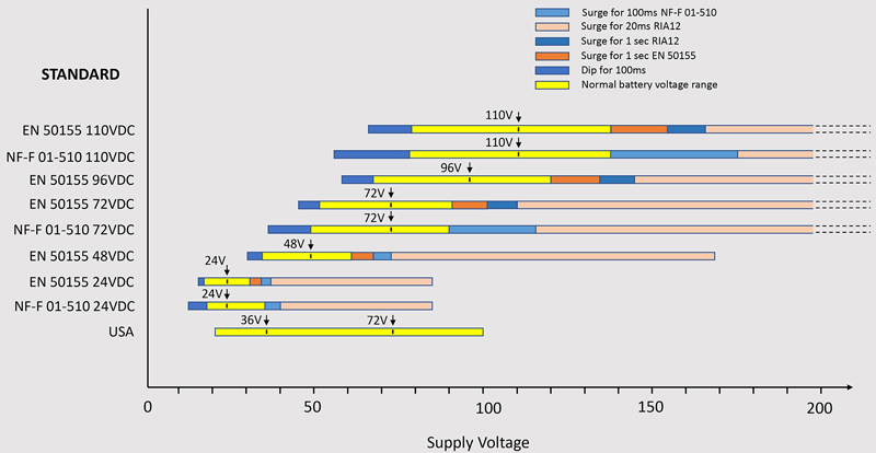
Figure 1: Various rail nominal voltages, dips, and surges
DC-DC converters used in onboard rail applications must meet challenging electrical supply and environmental specifications. The widespread adoption of the European Train Control System (ETCS) at the heart of the European Rail Traffic Management System (ERTMS) is setting new, more stringent requirements for power conversion devices.
Further investment in rail rolling stock is required to reduce carbon footprint while increasing the safety, capacity, and interoperability of rolling stock across borders. For example, in Europe, the ongoing transition to the single ERTMS European signalling and speed control system is helping maximize the interoperability of railway systems, increasing the speed, capacity, and safety of rail transport.
According to analysts, Research and Markets, the global rail market, including passenger and freight, will increase from around $500B in 2022 to around $846B in 2030. Electrification of networks is one area of expansion, mirroring the general move away from fossil fuel power. At the same time, remote condition monitoring, automation, and communications are being built-in. For example, the European Train Control System (ETCS), an automatic train protection system (ATP) that replaces the existing national ATP systems, continuously supervises train movement to maximize safety. Additionally, passengers expect more facilities, such as infotainment and wireless connectivity.
Investment in rail networks will be further boosted by the ‘Future Railway Mobile Communications System’ (FRMCS). This standard for digital communications will replace the existing GSM-R system, which is successful, with more than 200,000km of tracks eventually to be operated through the standard. However, support for GSM-R is set to end in 2030 prompting the rapid development of FRMCS which has an objective to become the worldwide standard.
In all rail settings, passenger, freight, over- and under-ground, power conversion equipment is needed for these ancillary functions, which will often be safety-critical, so equipment must operate reliably in a hostile environment.
The challenge for rail power conversion equipment
Historically, rolling stock across markets has had multiple system battery voltage nominal values for ancillary equipment, from 24VDC up to 110VDC, with variations and tolerances that also depend on geography. European standard EN 50155 is commonly used, along with the French standard NF-F 01-510, which has some variations, while older standards such as RIA12, originating in the UK, continue to exist. In the US, tolerances on 24V and 72V rails are different again. Figure 1 shows a selection of nominal voltages seen, their static tolerances, dips, and surges.
A challenging specification to meet is the requirement in RIA12 to withstand 3.5x nominal voltage, or 385V in 110VDC systems for 20ms, from a relatively low source impedance of 0.2 ohms. A varistor or TransorbTM cannot clamp this because of the energy that would need to be dissipated, so it must be regulated to within the equipment's normal working voltage range. Additional to the high-energy over-voltages listed, there are fast, high voltage, but low-energy disturbances, as defined in Rail EMC compatibility standard EN 50121-3-2, which calls up the ‘EMC Directive’ series of standards, IEC 61000-4. For example, +/-2kV with a rise/fall waveform of 5/50ns with a 5kHz repetition rate must be withstood with no interruption to function or damage.
According to EN 50155, complete supply interruptions can occur at the other end of the scale, graded S1, S2, and S3, the most severe, with 20ms loss of supply and no performance degradation allowed. These interruptions are assumed to be caused by momentary short circuits on the supply, so any power converter must have protection to avoid reverse input current flow. Equipment may also be required to continue without interruption under 'supply changeover' conditions, for example, between redundant power sources, when the supply is momentarily open-circuit. In this case, two classes are defined: C1, a 100ms interruption from 60% of nominal voltage with no effect, and C2, a 30ms interruption from nominal voltage with some degradation of performance allowed.
Standards also apply for radiated and conducted RF emissions, identified in EN 50121-3, -4, and -5.
The various levels of immunity and allowed equipment response to surges, transients, dips, and interruptions are particular to the end-equipment function. They will be different for infotainment compared with safety-critical signage, for example.
The mechanical environment is also severe
Rolling stock has various environments where electrical equipment may be installed. These locations are classified from 1, the most benign, typically within passenger compartments, to class 7, which might be axle-mounted, experiencing high levels of shock, vibration, water, and pollution from dirt, brake dust, fuels, and fluids generally.
Fortunately, most ancillary electronic equipment requiring DC-DC power converters is mounted in the interior, mainly weather-protected location classes 1-3. These would be pollution degree (PD) 2 and 3 according to EN 50124-1 and category 1B for vibration and shock according to EN 61373. In addition, there are operating ambient air temperature classes for equipment, from OT1, at -25°C to +55°C up to OT6 at -40°C to +85°C. Rapid temperature changes can also occur, for example, while running through tunnels, with the worse expected to be +/-3°C per second.
Of course, power converters in rail applications are expected to be reliable and have a long service life to ensure the lowest lifetime cost and minimum downtime. A guarantee of continuity of supply for ten+ years is also essential.
Converter choices for rail applications
Given the typical rail specifications, ‘standard’ commercial parts are seldom a good solution. Although COTS products might meet selected performance parameters, they will typically have no long-term guarantee of support, and multiple parts would be needed for ranges of rail applications. Many available products also have limited isolation rating – perhaps only functional, whereas higher grades, basic or reinforced, are often required. COTS parts will also typically require extensive support circuitry to meet the EMC and supply variation specifications, consuming space and increasing component and assembly costs.
Difficulties in meeting a general specification for DC-DC converters for the application scale with the power level involved; EMC filters are larger and more complex as power increases, capacitors for hold-up during dips and interruptions are larger and achieving a wide input range is more difficult at higher power, with converters having to withstand high current stress at low input voltages. At the same time, components have to be rated for the highest input voltage, forcing compromises in cost and efficiency. The result has been that DC-DC converters with the ideal wide input range, EMC, and environmental performance have been only available at very low power or have been bulky and inefficient at higher power levels.
Optimised rail DC-DC converters are becoming available
Recent products have become available that use innovative but elegant conversion topologies that have pushed up the power rating of board-mounted DC-DC converters while keeping to a very compact format and meeting headline rail specifications with high efficiency. For example, 80W in a package just 50 x 44 x 12.9mm, (Figure 2), with an ultra-wide input range of 12VDC to 160VDC/176VDC peak (rated 60W below 36VDC input) with reinforced isolation. As can be seen from Figure 1, this input range covers all of the normal input static tolerances from 24VDC to 110VDC nominals, along with the one-second transients defined in EN 50155 and RIA12 to 154VDC and 165VDC, respectively. Also covered is the 100ms transient to 176VDC defined in the NF-F 01-510 standard. At the low end, 100ms brownouts in all of the standards to 12VDC minimum are also within the converter range. This particular product is rated -40°C to +105°C case temperature suitable for any rail application and is potted to withstand harsh environmental conditions. Quoted MTBF and lifetime are very high (typically above 1000 khrs according to Mil HDBK 217F GB where the usual figure is more usually from 300 to 500 khrs for the same standard condition), aided by magnetic feedback, avoiding optocouplers and their long-term degradation issues.

Click image to enlarge
Figure 2: A rail-optimized 80W DC-DC converter with 12VDC – 160VDC continuous input range
Pre-conditioning modules handle higher surges and add other benefits
Compliance with the high energy surges to 3.5x nominal according to RIA12 is not always required in rail applications, so it is best handled by an optional ‘pre-conditioning’ stage which will typically regulate the voltage down to below 160VDC. The stage is offered as a module by the same supplier matching their DC-DCs at 80W, 40W, and 20W, with built-in reverse polarity/current protection, with filtering for immunity to the supply fast transients and conducted emissions generated by the DC-DC converter. The module also has a novel arrangement where a small boost converter keeps a capacitor at a constant high voltage, whatever the input DC rail is, down to 12VDC. If a supply interruption occurs, the capacitor is switched onto the downstream DC-DC converter input to provide hold-up. As the energy is stored at high voltage and the capacitor can discharge down to 12VDC before the DC-DC converter drops, only a relatively small externally-connected capacitor is needed to meet the EN 50155 Class S3 20ms interruption specification. The module is 48.5 x 40.7 x 12.7mm in size. It includes an enable input, a fault flag, soft start, over-temperature shutdown, and the surge limiting circuit protection against over-stress. An outline is shown in Figure 3.

Click image to enlarge
Figure 3: Outline pre-conditioning circuit to meet rail specifications available as a module


