Author:
Dr Peter van Duijsen, Technical Director, Simulation Research
Date
01/20/2013
 PDF
PDF
Click image to enlarge
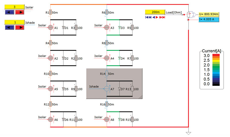
Figure 1: Shading and current distribution inside the solar module
The market for green and renewable energy is growing, but also presents numerous new challenges when it comes to technology, environment, and acceptance. Concerning technology, these challenges require not only new ideas, but also engineering effort to realize these new technologies. Reduction of cost and improving system efficiency are the two main engineering challenges. The traditional build and test approaches are both time-consuming and expensive. Also, building and testing does not provide enough insight to reach an optimal design, not even thinking about the costs and construction time. Use of engineering simulation software helps with the optimization of entire designs, whether it is a small-scale solar project or a large offshore wind park. Research for modeling and simulation in the field of green and renewable energy is a broad topic. Not only are the systems diverse, like wind and solar, but also the physical background of each type of green energy system varies greatly. For the modeling and simulation, this leads to two observations that design projects have to take into consideration: 1. Physical background of the underlying system 2. System or detail of the model of systems under investigation First, for example, wind energy requires knowledge of electromagnetic energy conversion, while solar requires knowledge of semiconductor devices. Control in solar systems is mostly a sort of smart search algorithm that finds the optimum electric load for a solar module, while in wind power systems, the control is clearly dependent on the wind speed. Fuel cell, reformers, and batteries require knowledge of chemical processes. So, generally speaking, various technologies are used when working with green-energy systems. Second the components can be modeled as simple system blocks with clearly defined functions but, on the other hand, multilevel models including all details can model them. For example, generator modeling in FEM and detailed semiconductor models in solar modules. The first step is to get an overall picture of the power distribution in the system and to look at the load of every single system component. Typically, idealized system components are used. On this system level, an early concept of the control system can be designed and tested in simulation. For example, the MPP (maximum power point) control method can be tested together with the solar module, DC converter, and grid connection. Another example is the overall energy harvesting of a grid-connected wind turbine for varying wind speed. The second step is to look at each component in more detail on the circuit level. One method is to replace the idealized system models with more detailed models. This increases overall simulation time, but gives more detailed simulation results. For example, a model including the semiconductor switches (IGBTs, MOSFETs, and diodes) could replace the ideal continuous model of a grid-connected inverter. The simulation results would now also include harmonics as well as typical modulation influences. The third step would be to look at each component in more detail on the component level. Instead of using more detailed lumped circuit models with limited parameter sets from the second step, the models could be based on more detailed engineering software. For example, a non-linear model replaces the three-phase generator circuit model, where the input-output relations are pre calculated in FEM/BEM (finite- and boundary-element method) software. Let's have a look at a number of typical simulation studies that give insight into the system. We start with a solar module containing a 4- x 3-cell array that, for some reason, is partly shaded. This is simulated on the second level (circuit level), since we want to know how the shading influences the behavior of the solar module (Figure 1). Here each solar cell is modeled using a sunlight dependent current source and a parallel diode and, yes, the diode is drawn in the correct direction. If the voltage across the solar cell gets beyond the typical on-state diode voltage of around 0.6 to 0.7 V, the diode starts conducting and short circuits the solar cell current. In figure 1, color indicates the intensity of the current: red is maximum current and black is zero current. The shaded cell current is zero and this shaded cell blocks the current from the other cells that are in series with the shaded cell. Shading one cell means turning off a complete column in a module and therefore bypass diodes are included. However, bypass diodes also reduce the efficiency, while increasing the costs of the rotor module.
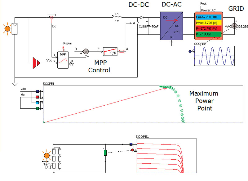
The second example shows the control of a grid-connected solar system. Figure 2 shows the circuit model including the MPP control and grid-connection control. A detailed second-level circuit model that includes load dependent loss and temperature dependency models the solar module. A boost converter that regulates the MPP for the solar module electrically loads the solar module. The boost converter is also modeled as a second level circuit model. The MPP controller is a first level system model that calculates the derivative of the power as a function of the voltage of the solar module. Together with the first level system model for the PI controller, the amount of power harvested by the solar module is maximized. The last part is the grid connection. Here a first level system model for the inverter and control is used. In the next example a more detailed model of a generator for a wind power system is examined. The efficiency of a wind power generator has to be optimized for two main reasons. First to maximize the amount of power the wind turbine generator can deliver and secondly to reduce the losses inside the generator. Each reduction of loss in the generator means that the generator delivers more output. Even 1% efficiency improvement is important when thinking about an average off-the-shelf 2 MW generator. An improvement of 1% means a reduction of 20 kW of loss that does not have to be cooled and 20 kW more that the system can deliver to the grid. Therefore, the bottom line in generator design is to optimize the generator efficiency over a wide operating range.
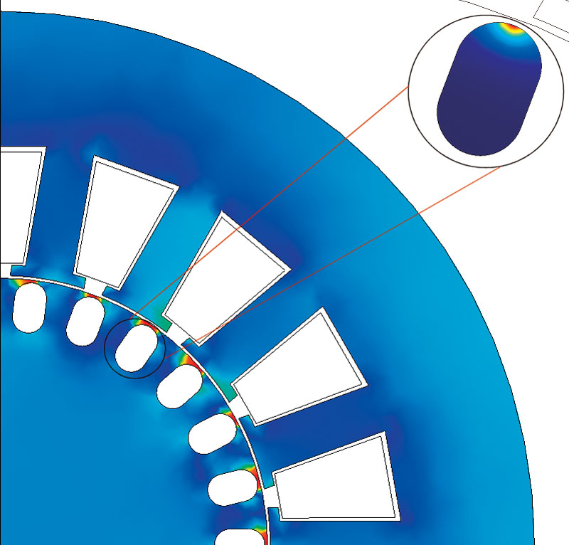
Specialized FEM software that can model the generator in detail with manufacturer data for magnetic and ferromagnetic material is used here. Especially hybrid FEM/BEM solvers are in favor, since they do not require meshing of the airgap and therefore are more accurate than FEM-only solvers. From the hybrid simulation, look-up tables are generated that can be used in the system level or circuit level simulations. Figure 3 shows the current distribution inside a rotor bar of an induction generator. Depending on the slip of the generator, the current distribution varies and, thereby, also the losses inside the rotor. The concluding example shows an overall system simulation of a wind power system. A more detailed second-level circuit model can replace every single component in this first-level system simulation. Also third-level component models or even a mix between first-, second-, and third-level models would be possible in this type of simulation.
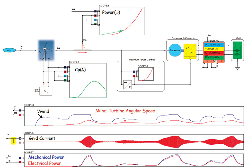
Figure 4 shows a grid connected wind turbine system with optimum power control. The maximum amount of power a wind turbine can deliver is equal to k?3. Therefore, the control electrically loads the wind turbine generator such, that it subtracts exactly k?3 Watts from the wind turbine and thus keep the system in equilibrium. For varying wind speed, the control directly adjusts the amount of power drawn from the wind turbine generator and also controls the amount of power delivered into the main grid. A second-level circuit model simulates the wind turbine, where the ratio between the wind tip speed and rotor angular speed determines the amount of power the wind turbine can deliver. This model is a minimum requirement when investigating the behavior for varying wind speed. The generator is modeled as a first-level system model, as the primary goal is to study the stability of the overall control system. Simulation Research