Modulating Charging Current in Battery Charger Applications
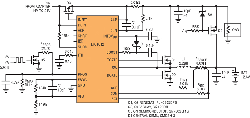
The LTC4012 is a very popular multichemistry battery charger used in a variety of applications. This controller provides the user with gate drivers, current sense inputs, temperature qualified charging and multiple signal outputs. There is also a range of useful functions detailed in the datasheet. One of these is the ability to change or modulate the charging current during the normal operation This feature is actively used in systems with limited input current. A good example is computer systems powered by a wall adapter, where the power and current capability of the adapter are limited. Yet the CPU and memory might demand a good portion of this limit. Obviously, in this situation, it’s a good idea to reduce the battery charging current in favor of the CPU demands. The programming of charging current is based on external transistor control by the signal with variable duty cycle, see Figure 1, which incorporates the circuit “Programming PWM Current” in. The goal of the article is to establish the region where charging current is linearly proportional to the duty cycle of the control signal.
Click image to enlarge
- Figure 1: Electrical schematic of the LTC4012 Li-Ion battery charger with PWM of the charge current
Circuit Description & Functionality
The solution in Figure 1 includes the LTC4012 battery charger and power train combining MOSFETS Q1, Q2, inductor L1 and input output filter capacitors. In case of a power failure or brownout the MOSFET Q3 disconnects the charger from the input lines and MOSFET Q4 connects the battery to the load. The duty cycle of the control pulse signals on the gate of the low power MOSFET Q5 modulates the charging current flowing to the battery BAT.
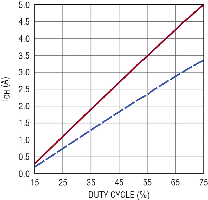
The charger based on the LTC4012 was used for testing different batteries and charging current levels. The linear region of the function charging current value vs. duty cycle of the control pulse signals lays between 15% and 80% of the duty cycle. If the duty cycle exceeds 80%, charging current tapers off and ceases to increase; conversely if the duty cycle is below 15% then charging current sharply falls. Figure 2 illustrates this, showing a perfectly linear region between 15% and 80% duty cycle of the control pulses applied to the gate of the transistor Q5.
Click image to enlarge
2.Graphs charging current vs. PWM duty cycle for 3.3A & 5.0A maximum charging current
Calculation for Programming Charge Current Resistors
Considering the limitation imposed by the PWM maximum duty cycle as 80%, resistors which determine the charging current in Figure 1 can be calculated per the following expressions:

where RSENSE is the battery current sense resistor.
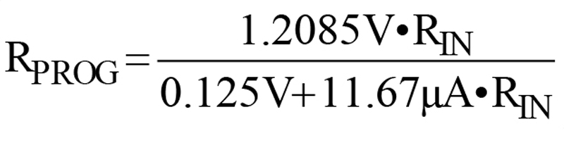
RP is the total impedance of RMAX and RPROG connected in parallel at 80% duty cycle

RPROG is a resistor connected to Q5 and switched by the 50kHz pulses variable duty cycle.
For a Li-Ion battery with a maximum charging current of 3.3A, assuming RMAX as 511kΩ, RIN as 3.01kΩ and maximum duty cycle as 80%, the RSENSE is calculated to be 0.03Ω, RPOG as 23.7kΩ. Figure 2 presents functionality of the charging current vs. duty cycle of the control pulses for this battery. A different battery with 5.0A maximum charging current was tested as well (RSENSE 0.02Ω, RPOG 23.7kΩ); see the graph of charging current vs. duty cycle presented in Figure 2.
Conclusion
The LTC4012 is a very popular battery charger used in many industrial and commercial applications. Systems that employ low power voltage sources often use pulse width modulation for limiting and programming Li-Ion battery charging current to deliver available power to key elements of the application. In this situation, the PWM duty cycle should be limited in the range of 15% to 80%.
Analog Devices