Percolation phenomenon affects long-term reliability
Figure 1: Typical components on SMCs
In DC/DC converters with higher switching frequencies, compact molded inductors enable smaller designs but often must cope with higher voltages and are exposed to higher temperatures. Both effects can lead to an increase in magnetic core loss over time due to material degradation related to the percolation phenomenon, which is explained in this article.
For DC/DC converter applications molded power inductors enable both smaller footprints and lower profile due to the properties of the magnetic material. The reduced dimensions of modern designs demand the employment of smaller inductors capable of operating at elevated voltages and currents in more extreme thermal conditions. The higher electrical and thermal stresses can lead to an increase in magnetic core loss over time due to material degradation related to the percolation phenomenon. Würth Elektronik has pioneered the introduction of this phenomenon as the common failure mechanism underlying the material degradation found under high voltage operations [1] and the degradation observed when a molded power inductor is exposed to high temperatures [2].
But what is this percolation phenomenon? What are the repercussions of percolation in a molded power inductor? And more importantly, how does it affect the long-time performance of a DC/DC converter?
Percolation phenomenon
Historically thermal aging tests performed over extended periods of time at elevated temperatures have been used to verify the reliability of magnetic materials, magnetic cores and inductive components. The options for evaluating the operating voltage on power inductors are limited to burn-in testing or voltage impulse testing to assess the effects of transient voltages on insulation integrity. In the specific case of molded power inductors, a form of progressive degradation in terms of performance at higher frequencies has been found by Würth Elektronik, when testing them at higher voltages or higher temperatures. The failure mechanism refers to the appearance of some “micro conductive networks” between the metal powder particles of the core material. This increase in the material conductivity causes an increase in core losses, eventually over time exhibiting a percolative behavior. The percolation threshold is the critical point where the material turns from insulating to conductive.
Percolation has generated great interest in the scientific community for decades and has promoted the development of theoretical models and experimental research work in understanding the connectivity phenomenon [Literature list in 3]. It has been used from traffic analysis, artificial intelligence programming, to materials design. In the materials field, percolation theory is a type of analytical-mathematical model, commonly referenced in the literature for the development and modeling of electrical conductivity in different materials [3].
Percolation theory originally refers to the slow movement of liquid through a material with tiny spaces or holes, as well as describing the behavior of a network when nodes or links are created. Percolation behavior occurs when interconnected pathways are formed within a material.
For composite material, percolation phenomenon occurs when the increasing amount of added conductive metallic particles reaches a point where the electrical conductivity increases abruptly. This is called the percolation threshold [3]. Many experiments have demonstrated that the conductivity of composites have a nonlinear relationship with the doping of conductive particles [3]. Composites are materials made by combining two or more elements, natural or artificial, which are stronger together than individually.
In the case of molded power inductors, the preferred solution for better performance is Soft Magnetic Composites, or SMCs. These composites are advanced materials engineered for their magnetic properties. Unlike traditional magnetic materials, SMCs are comprised of iron alloy powder particles coated with a thin insulation layer dispersed in a non-conducting matrix, such as epoxy or polymer binder. Molded power inductors based on SMCs depend on the insulation layer and binders to reduce the overall amount of eddy current losses, i.e. conductivity between particles [2], as shown in Figure 1.
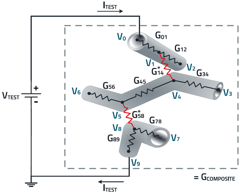
However, researchers have found that at high voltages or high temperatures, the phenomenon of conductive percolation also occurs even when the number of conductive materials added to a polymer is small [3]. The theory suggests that, under the action of a strong external environment, such as a high electric field, conductive particles collide with each other more frequently, leading to the movement of electric charges. This charge movement can generate electric currents and contribute to an emissive effect, allowing electrons to overcome the insulation layer in a material [Literature List in 3], and it can be associated with unfavorable or even a destructive effect [3]. In fact, we have found that with more current due to high voltages or with the continuous exposure to higher temperatures, the loss of the insulation properties of the binder and the coating layer itself induces the creation of more micro conductive networks, i.e. the percolation phenomenon in SMCs. A schematic illustration of the percolation network in composites [3] is used to clarify the concept, as shown in Figure 2. In the figure the red resistors represent the new conductive connections between the exposed iron particles of the material itself. This connection leads to the creation of clusters that can deteriorate the molded power inductor, from small areas to the complete material.
Click image to enlarge
Figure 2: Equivalent electrical circuit used to illustrate the growth of a percolation network on composite materials
As summary, we define the percolation phenomenon in a molded power inductor as the material degradation that transitions from an insulating to a conductive state, due to higher voltage or higher temperature, increasing the core losses due to larger eddy currents.
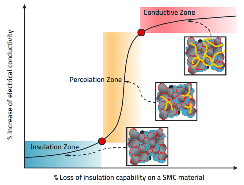
The non-linear relation between the loss of insulation and the increase of electrical conductivity (illustrated as the yellow networks) in a SMC is shown in Figure 3.
Click image to enlarge
Figure 3: Progression of percolation in molded power inductors
When the loss of insulation is below the threshold, the conductivity of the composite material increases slowly with the increase of the temperature or the applied voltage. However, when the material is exposed to higher voltages or higher temperatures, the conductivity increases leading to the percolation threshold. At this point, the percolative path passes through overlapping the binder, around iron particles, by creating clusters. Over time, the conductive paths of the material increase dramatically, and change it from an insulating material to a conductive material. It is a non-reversible phenomenon and compromises the performance of the affected inductor.
Repercussion of percolation
As has been presented, the percolation phenomenon appears during the lifetime of a molded power inductor, and it is difficult to identify at early stages. A molded power inductor with AEC-Q200 qualification for higher temperatures, over 125°C, can suffer from percolation, which cannot be detected with the usual pre and post measurements as the standard is recommending. This has been explained in [1; 2].
The common findings reveal that a compromised part does not significantly change the inductance or resistance value when measured at low frequencies (i.e. 100 kHz). However, when an impedance analyzer is used at high frequencies (i.e. 2 MHz), the Q value reveals a performance decrease.
To corroborate the percolation phenomenon due to higher voltage or higher temperatures, a new test setup has been prepared. A total of 20 samples of a 4.7 µH molded power inductor were taken from the same production lot number, all with similar electrical properties. For the series of tests, ten chokes were subjected to a high-voltage test and another ten to a thermal aging test. The measurements were carried out at an ambient temperature of 20 °C in each case.
The degradation mechanism was triggered by the continued exposure at a temperature of 160°C for an extended period of 300 h for the aging test. The high voltage test was accomplished by using a modular impulse generator to expose the inductors to a series of controlled pulses.
In the high voltage test, the first sequence of voltage pulses was chosen to be 120 Vdc, which is the limit recommended by the manufacturer’s datasheet. The applied pulses had a duration of 36 µs per pulse, following the recommendation of the IEC61000-4-5 standard for the rise and fall time of the pulses. In total 35 pulses were applied to each inductor to assess any impact.
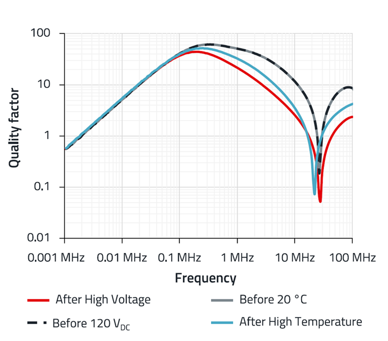
After that validation, the inductors were subjected to an overvoltage round of pulses. The summary of pre and post test results is shown in Figure 4.
Click image to enlarge
Figure 4: Change of the Q factor due to high temperature or high voltage exposure
The gray line refers to the average quality factor Q vs. frequency curve of the first 10 samples before exposure to higher temperatures, and the black dashed line corresponds to the other 10 samples after the first round of pulses at 120 Vdc. As can be seen, both curves show the same behavior. The red line corresponds to the average of the Q value vs. frequency after high voltage exposure with pulses around 190 Vdc and the blue curve to the 160°C test.
The voltage of 190 Vdc represents a 60% increase over the voltage limit supported by the non-conducting matrix mentioned earlier. From previous experience with the selected inductor, a voltage of 240 Vdc generates cracks on the component within the first few pulses.
A total of 10 pulses of 190 Vdc were applied. No cracks have been found, but there is an evident change on the Q curve. The blue line, the average Q after high temperature exposure, exhibits an impact, as expected. In general, it can be observed, both average values of the tests, i.e. the increased voltage and the increased temperature, have the same reduction of the quality factor at higher frequencies and a small change in the resonance frequency.
It is necessary to remark that percolation starts at different points inside the core of the inductor due to the physical effects induced by the test, which could be associated with either electrical or thermal percolation.
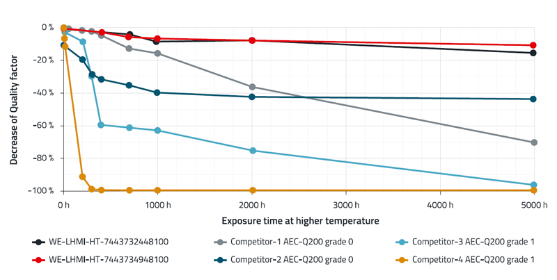
However, the trend is undeniable. Furthermore, with more exposure time the percolation will lead to a continuous decrease of the Q curve in a shorter time [2]. The results for the case of thermal aging degradation at 200°C for 5000 h is presented in Figure 5.
Click image to enlarge
Figure 5: Decrease of Q value at 2 MHz during 5000 h at 200°C
The measurement results demonstrate that even the products of the best competitors show a decrease of the Q value greater than 40% while the high temperature version of our new family WE-LHMI 7443732448100 and WE-LHMI 7443734948100 show a minimal decrease in performance.
At this point, it is necessary to remark that the posttest curves presented on Figure 4 do not correspond to the final conductive phase. If a molded power inductor has reached its limit, as the case of the competitors in Figure 5, even if the part presents some cracks, the coil will still conduct as a power inductor, however, with significantly different electrical properties compared to the original specification, affecting the application where it is used.
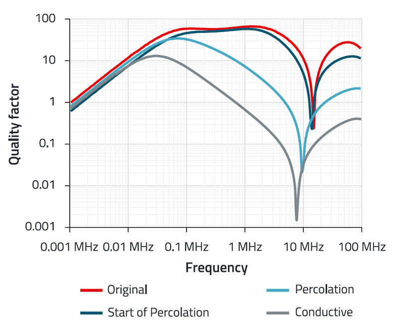
To relate the percolation level on the quality factor curve vs. frequency curve, the measurement results for the same inductor of 4.7 µH under a long-term stress condition are presented in Figure 6.
Click image to enlarge
Figure 6: Decrease of Q value due to percolation phenomenon
In summary, the percolation in molded power inductors could be identified as the decrease of the quality factor and inductance at high frequencies as well as the decrease of the resonance frequency depending on the progress of the phenomenon per se.
As a designer, you may be questioning at this moment, how long a molded power inductor with percolation problems can work without failure if used at high temperatures or high operating voltages?
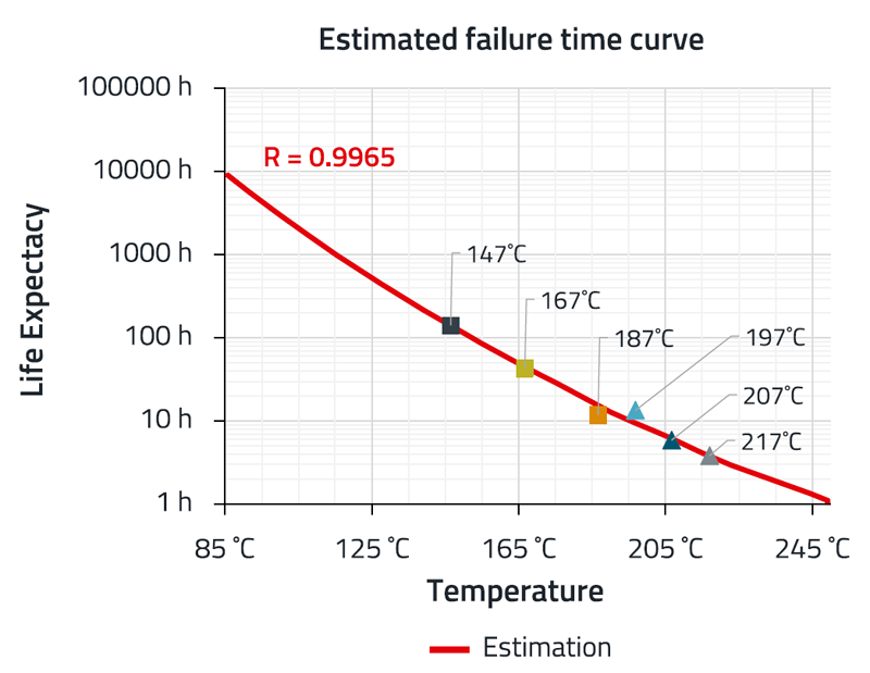
To solve this doubt, an Arrhenius Plot, presented in Figure 7, has been built following the recommendations found in IEC 60216-1 Electrical insulating materials, Thermal endurance properties, Part 1: Ageing procedures and evaluation of test results; in combination with the equivalent ASTM D 2307 standard. As the end point criteria, a decrease of 40 % in the measured Q value at 5 MHz was established, which represents a critical increase of 100% of the AC losses for a competitor molded power inductor of 5.6 µH.
Click image to enlarge
Figure 7: Arrhenius diagram to estimate the percolation over time at different temperatures on the tested competitor component 4 (shown in Figure 5)
The curve in Figure 7 shows that the competitor part fails after the first 100 hours of continuous exposure at a high temperature of 147°C. One might assume that by using the inductor at a moderately high temperature, slightly above the reported maximal temperature 125°C, it will not fail.
However, as demonstrated by the estimation derived from the Arrhenius plot, with a robust confidence interval (R²), even if the inductor is operated at 85°C, it is expected to fail after approximately 10,000 hours of continuous service, which corresponds to slightly more than one and a half years. Nevertheless, most industrial applications are typically designed for a service life of at least 10 to 20 years.
In contrast, WE components offer a projected lifetime of more than 20 years of continuous operation. In the performed tests, the components did not reach the end‑of‑life criterion that is used to extrapolate the Arrhenius plot. Reaching this criterion would require subjecting the components to temperatures exceeding 250°C, which is well beyond the maximum limits recommended by raw‑material suppliers. Such conditions were not applied in the conducted tests.
How is percolation affecting DC/DC converters?
How does the percolation phenomenon affect a real application? Today, semiconductors like GaN and SiC switching transistors with very short switching times and high maximum voltage capability get more interest from designers.
Meanwhile DC/DC converters are popular, which are performing with switching frequencies over 1 MHz, for example, in Power Supply on Chip (PwrSoC) aiming for higher efficiency with compact embedded designs for artificial intelligence applications. All of these show a trend in maximum power demand, high-frequency voltage stress and inductor energy. However, many molded power inductors from well-known manufacturers will fail under these new operating conditions due to the percolation phenomenon.
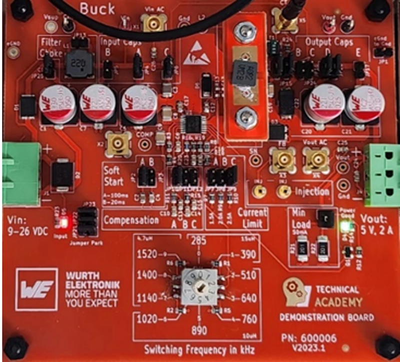
To demonstrate the possible effects of percolation, a conventional buck converter (step-down converter) with Vin = 14V, Vout = 5 V @ 1.3 A, operating at 1020 kHz is discussed in more detail in Application Note ANP142 from Würth Elektronik [3]. Figure 8 shows the buck converter, which has been tested. Particular attention has been paid to the aspects of efficiency and EMC. A detailed breakdown of the results, data interpretation, and implications for future designs is available in ANP142.
Click image to enlarge
Figure 8: DC/DC converter for testing the effects of the percolation phenomenon
References
[1] Frankemölle, A.; Lang, A.: Voltage specification for molded inductors, Application Note ANP126 from Würth Elektronik. www.we-online.com/ANP126
[2] Farnos, C.; Bernal-Alzate, E.: Introduction to thermal aging in molded power inductors, Application Note ANP128 from Würth Elektronik. www.we-online.com/ANP128
[3] Bernal-Alzate, E.: Effects of molded power inductor degradation due to higher voltage or temperature
in a DC/DC converter. Application Note ANP142 from Würth Elektronik. www.we-online.com/ANP142