Hot-swap circuits are predominantly used in high-availability systems, such as data centers and telecommunication infrastructure
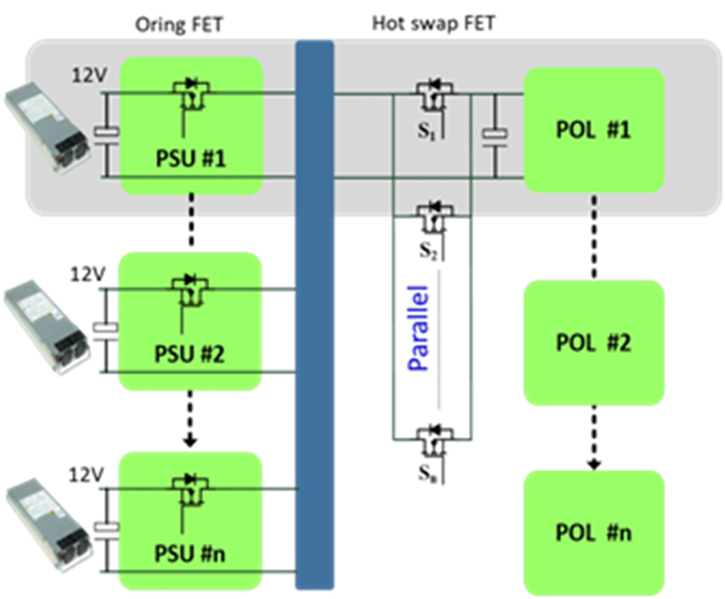
Figure 1. Multi-module Telecom-server Hot-Swap Applications
When hot-swap circuits are used in high-availability systems, the operation will not be interrupted if there is a need to replace or add attentional units for system operation.
Figure 1 shows that hot-swapping can often involve a large transient current (up to hundreds of amperes) to charge the output capacitors, which require a robust MOSFET with a large SOA capability during the linear operating mode. For high power and high redundancy, which are critical in telecom-server applications, a hot-swap controller is needed to regulate the inrush transient current. In telecom-server applications, the backplanes, terminal voltages which dominate are at 48V and 12V. In typical 12V backplanes, systems are made up of redundant power supplies, and each connected to the parallel hot-swap modules by the O-ring-FETs. The MOSFETs play a key role in the hot-swap application; thus, this article will evaluate the MOSFET behaviors based on 12V ADM1278 hot-swap circuits from ADI.
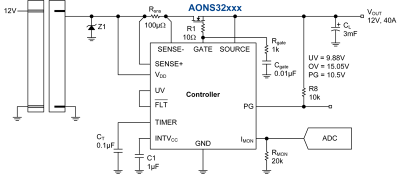
When the hot-swap module, as shown in Figure 2, is inserted into the 12V backplane, the controller GATE pin will source a constant 24uA Ig to the MOSFET gate as well as the shunt external Rgate and Cgate. After the GATE voltage reaches the MOSFET threshold VT, the Ig will only charge the external Cgate and MOSFET internal Crss because the voltage of Cgs across the GATE pin and the Vout node will remain constant. This is similar to the miller-plateau in the switching mode power supply.
Click image to enlarge
Figure 2. Hot-Swap Circuit Schematic
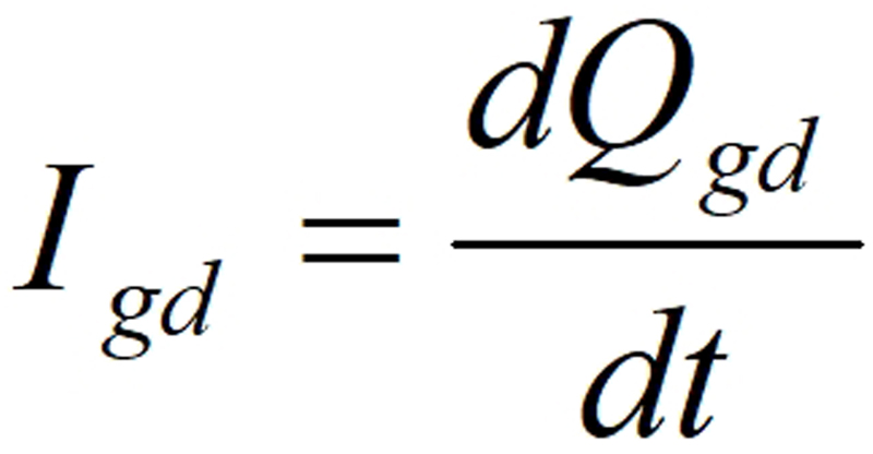
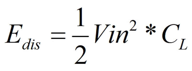
The inrush current Iin drawn by the output capacitor CL can then be expressed as the equation (1,2): Where ‘n’ stands for the number of MOSFET in parallel.
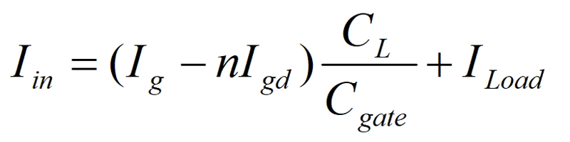
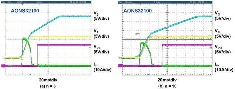
Unlike in switching power supplies, where low Qgd is preferred, larger Qgd may benefit from lowering inrush current in hot-swap applications. On the other hand, the inrush current is also determined by the number of parallel MOSFETs, the output capacitor CL value and the load current. The fewer parallel MOSFETs and the larger output capacitors will lead to larger inrush current stress on the MOSFET. Below are the test waveforms on AOS hot-swap evaluation boards for different scenarios. Figure 3a shows that a larger CL will draw a larger inrush current (green curve), while Figure 3b indicates that the increasing number of parallel MOSFETs will decrease the total inrush current (green curve).

Click image to enlarge
Figure 3a. Comparison of Start-up Waveform with No Load and Different Output CL
Click image to enlarge
Figure 3b. Comparison of Start-up Waveform with No Load, same CL 50mF but Different Number of Parallel MOSFET
Telecom-server hot-swap applications involve a large supply current during typical on conditions; therefore, a low Rdson MOSFET is most preferred. A large SOA is required to ensure the system's robustness during start-up and short-circuit conditions when MOSFETs are undergoing high voltage and current stress in linear operation mode.
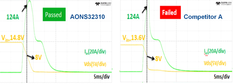
Figure 4 shows that AONS32310 has a lower inrush current than the competitors because of relatively larger Crss. This can ease the inrush current limit settings of the system, and the lower Rdson means higher overall efficiency. When the output cap value and input voltage increase, AONS32310 still worked while comparable competitor parts failed.
Click image to enlarge
Figure 4. Comparison of Start-up Waveform with No Load, same 70mF CL
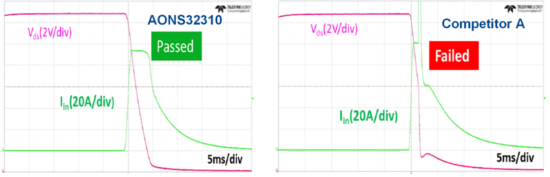
Figure 5 replicates a worst-case condition where the MOSFETs are on and at the thermal equilibrium of 100°C. There is a reset where the hot-swap controller has to turn back on where the MOSFETs are under elevated temperature (100°C).
Click image to enlarge
Figure 5. Comparison of Start-up Waveform with No Load, same 50mF CL Inside the 100°C Chamber Environment
These worst-case conditions demonstrate that AOS MOSFETs are robust for hot-swap applications compared to other competitors. Since the energy dissipated on the MOSFET is almost equal to the energy stored in the output CL, AOS proposed to use the equation (3) to determine how robust in terms of SOA capability.
On the other hand, if the same inrush current limit applies, the AONS32100 will exhibit almost identical start-up waveforms as the competitor C but need to adjust the external Cgate and Rgate. In hot-swap applications, the Cisswill not affect the gate voltage during the linear mode. The MOSFET is already fully on and the minimum delay of gate voltage will not make a difference in the system’s efficiency and performance.
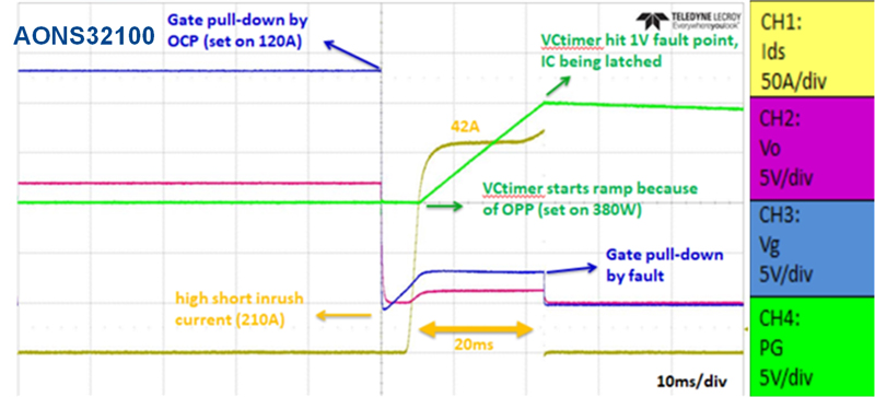
Even the best-in-class MOSFET cannot withstand the fault condition, such as output short for seconds. Therefore, the hot-swap controller is required to shut down the MOSFET as soon as possible by sensing the current and voltage stress. The ADM1278 from Analog Devices is capable of both overcurrent and overpower protection. In an overpowering event, the controller will not turn off the MOSFET until the fault timer voltage hits the fault threshold 1V. The timer can be set according to the SOA of the MOSFET, which gives the designer the flexibility to choose the MOSFET that fits the system requirements and avoids the unnecessary shut down during the start-up and transient events. Figure 6 shows a series of OCP and OPP events based on the AOS evaluation board. It can be seen from the waveforms that the AONS32100 can withstand 42A/9V for more than 20ms in linear operation modes during short circuit fault in the worst-case scenario.
Click image to enlarge
Figure 6. Short-Circuit Conditions and Protections
Selecting a robust MOSFET is essential to hot-swap applications where failure even during worst-case conditions is essential for high availability. The high SOA and lower Rdson contribute to higher efficiency enabling the system to be more robust capability.


