Multi-Dimensional MOSFET Modeling With Interactive Datasheets
The datasheet is typically the first port of call when a designer is looking for a discrete MOSFET to perform a specific function in an application
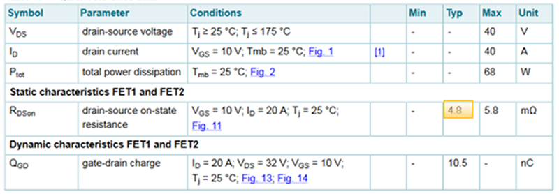
Figure 1: Reading MOSFET RDS(on) from a standard datasheet
Datasheets are often long and cumbersome, meaning locating and interpreting the required information is not always trivial. Furthermore, the meaning of the listed parameters is rarely explained in the datasheets, and even the slight differences in how they are interpreted can be critical for how a device behaves in an application. In addition, parameters are commonly specified for typical operating conditions, making it difficult for designers to determine how a device might behave in alternative scenarios. As a result, field application engineers employed by semiconductor device manufacturers spend considerable time assisting designers in performing calculations and assisting them interpolate datasheet graphs. Through a series of practical scenarios, this article discusses the benefits of a recently introduced and ground-breaking innovation from Nexperia – interactive datasheets – an entirely new way to gain insight into MOSFET behaviour that can be dynamically adapted for a custom application. This tool lets designers visualize the interdependence of several parameters simultaneously and quickly determine how a device performs at a desired operating point. The accuracy of these novel datasheets, which promise to significantly reduce the need for complex calculations and interpolation, is greatly enhanced by Nexperia’s recently released electrothermal models on which they are based. These are the first models to provide insight into the thermal behaviour of discrete MOSFET devices across their entire operating temperature range.
Scenario 1a: MOSFET RDS(on) at 25 °C, VGS = 10V
A designer wishes to know the RDS(on) of a MOSFET for VGS = 10V at a junction temperature of 25 °C. Reading from a table in a standard datasheet is straightforward, where the typical value for RDS(on) = 4.8mΩ is listed. (Figure 1).
Nexperia’s interactive datasheet for the same device feature ‘sliders’, which can be set to a desired MOSFET operating point (Figure 2). This datasheet provides a value of RDS(on) = 4.13mΩ. However, the figure more accurately reflects the actual value measured in a real application. The reason for the discrepancy between the two is due to datasheets being based on typical devices which may not necessarily represent the mean, while the precision electrothermal models on which the interactive datasheets are built on are based on devices that represent the mean behaviour. Conversely, the interactive datasheet behaves as a simple graphical user interface (GUI) to display the data generated by Nexperia’s electrothermal models. This allows the interactive datasheet to display MOSFET behaviour and dynamically calculate RDS(on) for the operating point selected with the sliders at near instant speeds.

Click image to enlarge
Figure 2: Reading MOSFET RDS(on) from an interactive datasheet
Scenario 1b: MOSFET RDS(on) at 100 °C, VGS = 10V
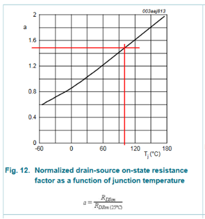
Next, the designer wishes to know the value of RDS(on) (for the same device) at 100°C. Using a standard datasheet to discover this value requires scrolling through several pages to find the graph showing RDS(on) normalised for temperature (Figure 3). Then, projecting vertically (using a rule) from 100°C to the point of the intersection with the curve and horizontally delivers a scaling factor of approximately 1.45 (bearing in mind there is a margin for error when reading the graph). Multiplying this value by RDS(on) (typical) gives an approximate value for RDS(on) = 7mΩ.
Click image to enlarge
Figure 3: Calculating a temperature scaling factor
Using an interactive datasheet requires them to simply move the Tj slider to 100°C and to read RDS(on) = 5.63 mΩ - once again, a more accurate and realistic value calculated by a circuit simulator using the device’s electrothermal models.
Scenario 1c: MOSFET RDS(on) at 25 °C, VGS = 5V
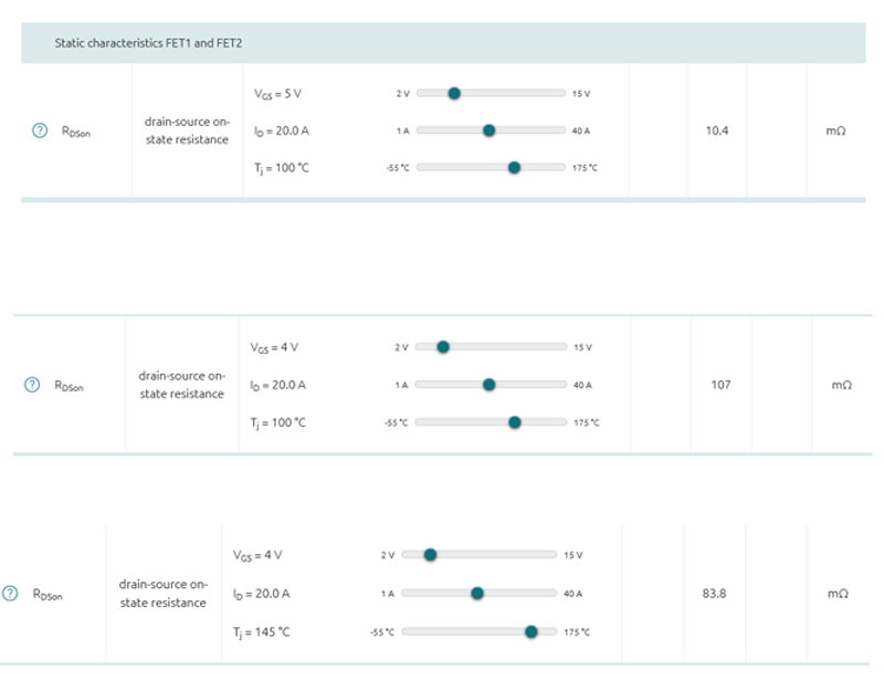
The designer now wishes to discover the device’s RDS(on) for VGS = 5V, also at 100°C. Unfortunately, using the information in a standard data sheet (irrespective of the manufacturer) is impossible. However, using an interactive datasheet only requires moving the VGS slider to 5V and then reading the value for RDS(on) = 10.4mOhm to get the required information.
Scenario 1d: Investigating temperature dependence
The designer wishes to investigate MOSFET temperature dependency and moves the VGS slider to 4V before reading the corresponding value of RDS(on) = 107mΩ (in line with expectations since resistance increases with increasing temperature). Next, they move the slider to 140°C but RDS(on) falls to 83mΩ (Figure 4). While this might initially appear questionable, this is attributable to the negative temperature coefficient of MOSFET threshold voltage, which the precision electrothermal models capture accurately in the value shown in the interactive datasheet. This behaviour would be almost impossible to deduce using the information in a standard datasheet, thus demonstrating this new tool's superiority, bearing in mind that only the value of VGS has been varied in this example. A different scenario may also require investigating the effect of varying Id, which interactive datasheets allow.
Click image to enlarge
Figure 4: Simultaneously investigating the effect of gate voltage and temperature on MOSFET behaviour
Scenario 2: PTOT
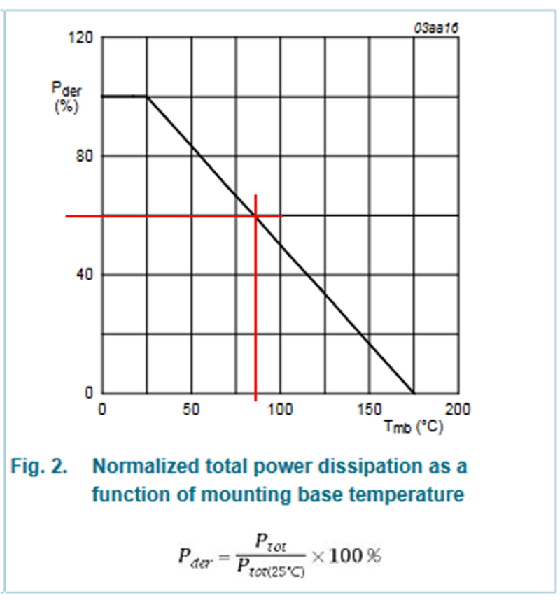
A designer wishes to know at what mounting base temperature a device can dissipate 40W (assuming ideal conditions, i.e. infinite heatsink). Before consulting a standard datasheet, they must first calculate the derating factor, which is 40/68 ≈ 60% for this example. Then they would need to find the page in the datasheet showing a graph of normalised total power dissipation as a function of the mounting base temperature. Then by projecting horizontally (manually using a rule) from 60% on the y-axis (Pder)to the point of intersection with the graph, then vertically to the x-axis before arriving at a Tmb value of 80°C (Figure 5).
Click image to enlarge
Figure 5: Manually calculating the temperature at which a device dissipates 40W
On the other hand, by using an interactive datasheet, a designer only needs to move a slider to a desired value to get the figure for calculated power loss. As shown in Figure 6, Tmb = 85°C in this example.

Click image to enlarge
Figure 6: Reading Tmb directly from an interactive datasheet
Other scenarios: Qg(tot), Qgs, Qgd and more
A standard datasheet states these for specified ID, VDS and VGS values, leaving a designer with no additional insights into how they vary during switching. Typically they could only get this information by performing a simulation of their application using SPICE tool, requiring both time and a degree of proficiency in using circuit simulator software. Interactive datasheets remove this requirement by allowing a designer to input the operating conditions for an application and calculate power losses directly. Allowing a designer to tune the operating conditions and quickly change application requirements rapidly increases the speed of iteration towards a final design.
Conclusion
It is impossible for manufacturers to provide an exhaustive list of device parameters for every scenario a MOSFET may encounter in an application, meaning they are restricted to providing such information for typical operating conditions. Furthermore, many parameters are dynamic and interrelated, but these relationships can be difficult to discern using a standard two-dimensional datasheet. Nexperia’s interactive datasheets represent an entirely new and multi-dimensional way to help designers understand how a MOSFET might behave in non-typical operating conditions. While retaining the familiar ’look and feel’ of a standard datasheet, they offer a user-friendly interface that interactively and dynamically calculates parameter values in response to changing user input.