The EPCOS PQSine active harmonic filter
To a non-engineer, the word “harmonics” has a beautiful sound – one that to many conjures up an image of a concert with instruments playing beautiful music. The harmony is what combines with the melody to turn the composition into something complex and beautiful rather than being just a simple tune.
However, when most design engineers hear the word harmonics it is often used to discuss an unwanted or secondary signal oscillation that can cause issues resulting in the impaired quality of an essential or primary signal. In this case, harmonics is not beautiful and complex, but complicated and unwanted. Harmonics become an unwanted pollution within the system.
When dealing with power quality, an increasing number of loads are designed to be non-linear and do not follow the sinusoidal voltage. Because of the non-linear nature of such systems, unwanted harmonics are introduced into the power grid which reduces the power quality. Harmonic filters can effectively reduce detrimental harmonics in such systems which increase the efficiency of the power distributed and lower power costs as well as decreasing equipment failures caused by poor power quality.
In fact, non-linear loads are now commonplace, making linear load design the exception rather than the rule. We see them in homes, offices, data centers, industrial facilities and other buildings. Non-linear loads are increasingly commonplace in the frequency converters and switch-mode power supplies of drive systems, telecommunications and other IT equipment, consumer electronics, household lighting and even electrical equipment at a concert hall.
Causes
However, each of these applications is at risk from unwanted harmonics. The non-linear current draw can cause interference for other loads by creating harmonics resulting in distortions in the sinusoidal voltage. Harmonics multiply the basic or line frequency (often 50 Hz or 60 Hz) and have varying amplitudes that can extend well into upper MHz ranges.
As a result of harmonics, any supplementary current load on the neutral conductor gradually increase harmonic currents and lead to inadmissibly high currents within the system. Phase-asymmetry is also a risk and can create additional harmonics, especially within switch-mode power supplies. This creates problems for other loads as the quality of grid power is reduced and otherwise negatively affected.
Consequences
Harmonics can also cause power surges and other issues that destroy or impair sensitive devices when they are transmitted through powerlines, high voltage wire and even low-voltage data lines.
The consequences of harmonics can be significant. It is not uncommon for data to become corrupted on servers in data centers due to harmonics in process controllers, costing organizations an untold amount dollars and lost time due to the loss of critical data, intellectual property and downtime.
Engineers often try to eliminate harmonics by using passive components, including capacitors and inductors, directly at the load. However, this is ineffective as there is an unlimited spectrum of harmonics, and such a design would require a well-tuned resonant circuit for each possible harmonic -frequency, which would be mathematically impossible and cost-prohibitive to address.
Active filters
Active harmonic filters offer a solution to compensate for many of the issues caused by harmonics in a fully automatic way. These filters are connected in parallel to the load causing harmonics in the grid. These ensure a sinusoidal current draw thereby significantly reducing harmonics and other phase shifts.
The most effective active harmonic filters for such applications are designed with a controller based on a 32-bit digital signal processor that has a sampling rate of 48 kHz and a response time of 21 µs, resulting in the highest performance available.
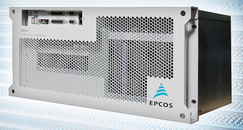
Some active harmonic filters, such as the EPCOS PQSine (see Figure 1), utilize a selective drive control (SDC) algorithm that are faster than traditional fast Fourier transform (FFT) algorithms. Such filters can feed compensation currents at real-time speeds into the grid, thereby cancelling the non-linearity of the load current.

Clcik image top enlarge
Figure 1: The EPCOS PQSine active harmonic filter
Balancing Loads
Newer active harmonic filters are designed for three-phase grids with or without neutral conductors with voltages of between 200 V AC and 480 V AC at 50/60 Hz. They can detect and filter harmonics up to 2500 Hz to 3000 Hz, and used in high quantities in 60 A steps until they reach their maximum compensation current of 600 A.
Conventional power factor correction only compensates for inductive loads. By contrast, active harmonic filters safeguard balancing of the loads to all three phases and can also compensate for capacitive reactive power components.
Modular Filters
A modular approach to harmonic filter design provides enormous benefits and high flexibility. In such a design, any 60 A module can be replaced as needed. And, standard control cabinets with 180 A filter performance can be easily expanded with up to five additional 60 A modules resulting in 300 A filter performance. Plus, each module has its own independent intelligence so if one module were to fail the user is still left with the remaining modules working and thus their site does not shut down as it would using standard non-modular systems. This is a very unique advantage of the EPCOS PQSine system.
Such a modular design requires active harmonic filters that feature plug-in connectors for both power connections and control cables. With this design, the modules can effortlessly be inserted into a wall-mounted or floor cabinet with a busbar that is designed for currents up to 300 A.
Self-monitoring
When selecting an active harmonic filter, designers should select parts that are self-monitored resulting in the highest overall reliability of the system. Items in particular that should be self-monitored by the system should include protection against overload and over-temperature, protection against over-voltage or under-voltage and fan monitoring.
Output Topology
The most effective active harmonic filters utilize a three-level, 12 Insulated-gate bipolar transistor (IGBT) topology with four IGBTs per phase conductor. Older and less-effective active harmonic filters utilize a two-level Insulated-gate bipolar transistor (IGBT) bridge at the output. Two-level output topologies are analogous with that of a 6-pulse frequency converter.
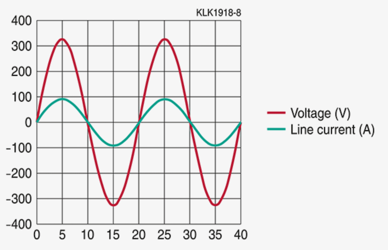
This newer three-level IGBT topology design for active harmonic filters achieve significantly superior approximation of a sinusoidal waveform to the output signal than systems with a two-level topology. Because each IGBT is only switching half of the operating voltage with a three-level topology, the outcome is substantially reduced switching losses (see Figure 2).
Click image to enlarge
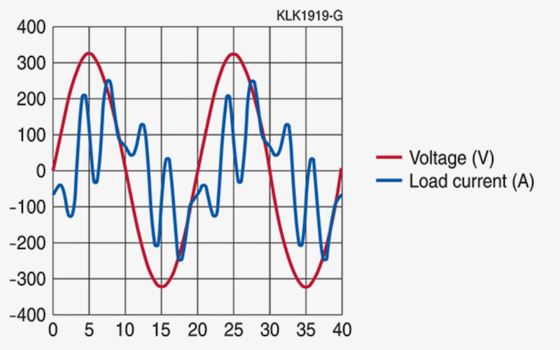
Figure 2a: The waveform without filter and with (b) an active harmonic filter
Clcik image to enlarge
Figure 2b: The waveform with an active harmonic filter
Music to My Ears
By selecting the most effective active harmonic filters for the design, engineers can reduce harmonics, resulting in a system that runs as smoothly as a concert played by well-seasoned professionals. When specifying parts, engineers should look for active harmonic filters that can balance loads effectively, are modular, are self-monitored and that have the correct output topology in order to reduce harmonics efficiently.
And, whenever harmonics is reduced, that is music to my ears.
 PDF
PDF