Author:
Bruce Rose, CUI Inc
Date
09/30/2021
 PDF
PDF
Click image to enlarge
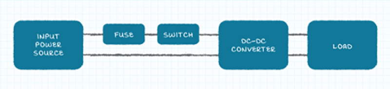
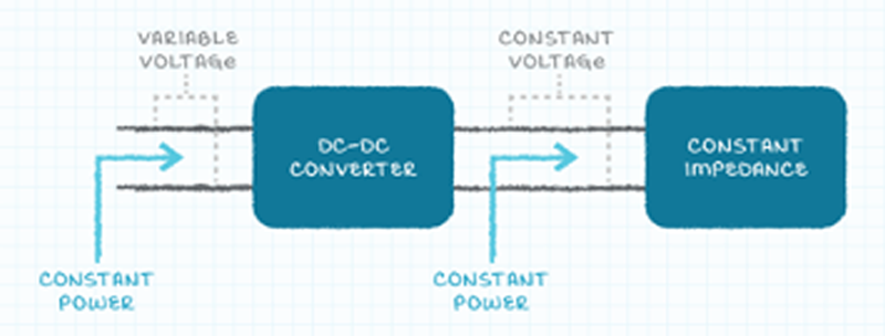
Figure 1: An example of a standard dc-dc converter application
If your DC-DC converter doesn’t work, you might check all the obvious causes that it could stem from - such as it not being plugged in correctly, not turned on, the input fuse having blown, etc. - none of which appear to be the issue. So you are completely perplexed as to why it won’t play ball. But, have you considered that the problemmight be due to the input impedance exhibiting negative resistance?
To find out if this could be the problem, you need to look at the input of the converter to ensurethe input impedance is not interacting with the output impedance of the input power source. If it is, then the converter’s output voltage will have a substantial ac component, as well as there also being an ac signal present on the input voltage at the converter.
Fundamentals of negative resistance
To begin, let’s consider the following scenario. You have a constant impedance load being applied to a dc-dc converter’s output, with the power supplied to this constant impedance load also being constant (since the device’s output voltage is similarly constant). The power supplied being constant indicates that a constant power is drawn by the converter’s input. The set-up outlined in Figure 2 will generate a power load that draws continuous power that is separate from the applied voltage.
Click image to enlarge
Figure 2: A constant impedance load added to a dc-dc converter
With this load arrangement, the following will occur:
● When the input voltage applied to the dc-dc converter increases, then the input current will decrease
● Conversely, as the input voltage directed to the converter falls, the input current will rise
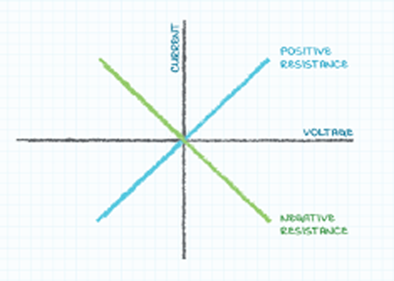
When the current and voltage are moving incrementally in different directions, you have a situation where there must be (in accordance with the principles defined by Ohm’s law) a negative incremental resistance. Of course, a positive incremental resistance is more common, with a rise in the applied voltage producing a rise in the applied current in turn. Likewise, a decrease in the applied voltage here will result in a decrease in the applied current.
Click image to enlarge
Figure 3: Schematic explaining positive and negative resistance
The impact of negative resistance
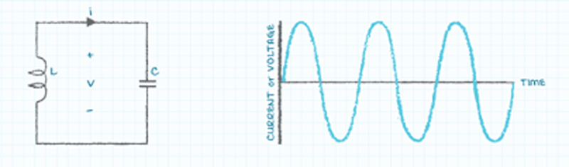
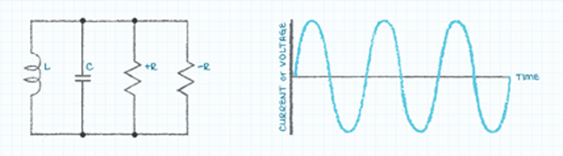
To understand the possible effects of negative incremental input resistance, it is useful to recognize how an electrical circuit comprising a capacitor and an inductor behaves. When energy is supplied to the capacitor and inductor circuit, an energy swap between the capacitor’s electric field (which stems from the voltage across the capacitor) and the inductor’s magnetic field (originating from the current passing through the inductor) will be witnessed. This exchange of energy effectively behaves just like an oscillating circuit - appearing as a sinusoidal voltage wave across the elements, and a current flowing through them.
Click image to enlarge
Figure 4: An ideal L-C circuit and associated voltage or current waveform (continuous sinusoid)
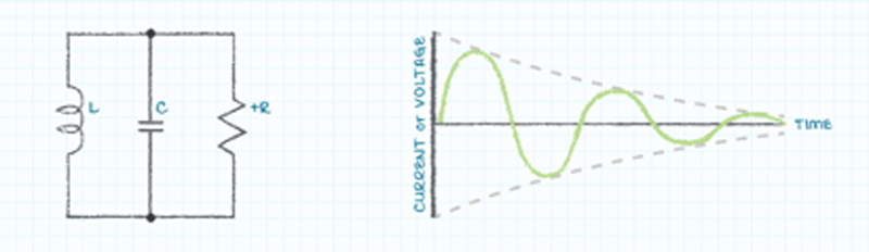
In actual circuits with capacitors and inductors, you will also see a parasitic resistance. This will disperse the energy over time until the oscillation eventually stops (as described in Figure 5).
Click image to enlarge
Figure 5: R-L-C circuit and associated voltage or current waveform (decaying sinusoid)
However, if you add negative resistance to the R-L-C circuit, it can cancel the positive resistance, thereby creating a circuit with zero resistance in the process. This will mean that the oscillations can continue indefinitely. It is possible for a circuit with inductance, capacitance and zero resistance to occur within certain operating conditions at the input of a dc-dc converter. Oscillation will be maintained if the negative input impedance of the dc-dc converter manages to cancel out the positive impedance of the associated capacitance and inductance (as shown in Figure 6), with the dc-dc converter’s operation thus affected.
Click image to enlarge
Figure 6: An R-L-C circuit exhibiting negative and positive resistance with the associated voltage or current waveform (continuous sinusoid)
It is important to be aware of the fact that the capacitance and inductance of the circuit can be physical elements, either of an intended or parasitic nature, or else synthesized by the output impedance of the power source together with the input impedance of the dc-dc converter. These synthesized elements have certain features meaning that as the system operating conditions change, their actual values will too. This can make it very difficult to accurately model the system associated with the dc-dc converter and to establish what the specific operating conditions will be for oscillation to take place.
Tackling negative resistance
While it might be a challenge to predict the conditions under which oscillation will occur, it is comparatively simple to include a positive resistance between the power source output and the input of the dc-dc converter. Through this, engineers can make certain that ongoing oscillation conditions are not maintained.
There are several possible routes to take here. Let’s briefly look at each of these:
● The first is to place a resistive element in series between the power source and the dc-dc converter.
● The second option is to add a resistive element in shunt across the output of the power source and the input to the dc-dc converter.
● The third and final option is to dc block the resistance from the circuit. The key advantage of this is that the resistance affects the oscillation, but does not have an impact on the desired power flow - whereas the power dispersed by either of the previous methodologies is frequently problematic, as it is too large.
One way to produce the required resistance is to add an electrolytic capacitor with a suitably large capacitive value adjacent to the dc-dc converter input pins (which is illustrated in Figure 7). This capacitor will normally need to have capacitance measuring in the region of tens to hundreds of µF. When the capacitor’s equivalent series resistance (ESR) is ac coupled into the circuit, it disperses enough energy to prevent continuous oscillation from taking place, but is blocked from the dc power path and prevented from dissipating energy connected to the dc flow of power (which would clearly otherwise be a major problem for the power system in terms of its efficiency).

Click image to enlarge
Figure 7: Electrolytic capacitor near the input pins of the dc-dc converter
Though this approach seems to be ideal, system designers should be mindful of the fact that the ESR of low-cost electrolytic capacitors may prove to be too high. This will lead to excessive power dissipation being seen. In complete contrast to that, the ESR values of high-cost electrolytic, ceramic or film capacitors may be too low to reduce the oscillations effectively.
Clearly a balance needs to be struck. The ESR associated with the chosen capacitor has to be small enough that it does not disperse too much power, yet large enough to successfully deal with the oscillations resulting from negative resistance conditions. There are electrolytic capacitors that are readily available which come with the correct ESR to be able to operate effectively in this scenario - providing the damping mechanism required to ensure the operational performance of the dc-dc converter is kept at the highest possible levels. The dc-dc converters offered by CUI benefit from superior design concepts and expert engineering. This means that the threat posed by negative resistance at their inputs can be avoided without there being any compromise on the operational parameters that they can attain.
Conclusion
A dc-dc converter represents a constant power load, delivering a constant power output. If there is a variation in the input voltage, then negative resistance effects will arise - with the input current going in the opposite direction to that of the voltage. This may subsequently bring about the conditions necessary for generating unwanted oscillations. Though this is potentially problematic, it is relatively straightforward to resolve. As long as engineers have a good understanding of the reasons for the advent of such a situation, then they can take the necessary measures to prevent it from happening.