Benefits abound from low DCR inductors
New inductors are introduced all the time. In such an established industry as ours, it is quite natural that many new products represent small, evolutionary improvements or solve unique problems. Occasionally, however, major generational breakthroughs do come along that challenge designers into new ways of thinking in order to take full advantage. This article will examine the latest game-changing inductor designs and how creative thinking designers go beyond the datasheet to make the proper inductor choice for the best converter design.
Inductors remain at the heart of power electronics. Selecting the correct inductor optimizes the reliability, size, and operating characteristics of a power converter. The clever designer knows the process of making a proper inductor choice cannot be taken for granted and cannot easily be captured in a handbook. After all, circuit requirements change with time. The inductor we wanted yesterday is simply not the inductor we want today. Trends include simple things like switching frequency, of course, but picking the optimal inductor also changes with the advent and proliferation of GaN devices to replace silicon MOSFETs, new controllers and control schemes, as well as the need to provide tightly regulated power from ever-wider Vin sources. These things mean old rules of thumb like “choose inductance value so ripple current = 40% of load current” may simply not always apply for the converter designs of today and tomorrow.
In addition to the evolution of what we ask our inductors to do, the basic nature of inductor operation encourages the use of careful thought to choose correctly. Inductors are passive devices that are far more interesting when something active is happening. Inductor performance is always determined by the operating/excitation conditions. All key parameters are dependent on something else: current depends on inductance as di/dt = v/L, but so too inductance depends on current as determined by the B-H curve. Inductance may vary with frequency for example, and, more subtly, is also impacted by wave shape: fast-rising edges on voltage pulses drive di/dt differently than a sine wave.
New Inductors
Let’s examine an example of a recent inductor development that presents a clear and immediate benefit, with even more optimization available to the designer willing to go beyond the inductor datasheet. Coilcraft’s XGL family of power inductors recently raised the performance bar significantly by lowering DC resistance. Since the new inductors are drop-in replacements for previous generations, comparisons can be readily made and the immediate benefit of lower DCR can be viewed in two ways.
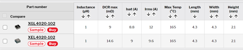
The lower DCR inductor can simply replace an existing one to decrease power loss and gain efficiency. For example, the very popular XEL4020-102 inductor can now be replaced with one offering lower DCR. Figure 1 shows a comparison of the specifications and the power-saving benefit of lower DC resistance. This is a simple and valuable improvement and the user has nothing to do other than drop in the new inductor and enjoy 38% more efficient current flow through the inductor.
Figure 1Low DCR Power Saving
Click image to enlarge

Click image to enlarge
Figure 1a & 1b: Power Saving Examples: For 10 Arms in each inductor
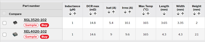
Another way to employ the value of such new inductors is to translate the high performance into a miniaturization opportunity. Figure 2 demonstrates this valuable space savings. Using the same XEL4020-102 as a starting point, the new inductor technology can provide the same DCR in a much smaller case size. Miniaturization is the top priority is many converter designs, and smaller inductor size usually enables a significantly downsized converter.
Click image to enlarge

Click image to enlarge
Figure 2a & 2b: Low DCR Size Saving
Beyond the Datasheet
The previous examples demonstrate that inductor developments can indeed be dramatic, and can directly contribute to desirable converter designs with either higher efficiency or smaller size. When a revolutionary advanced inductor family like Coilcraft XGL is introduced, some benefits are clear from the datasheet. However, such dramatic improvements bear further investigation for even greater optimization possibilities.
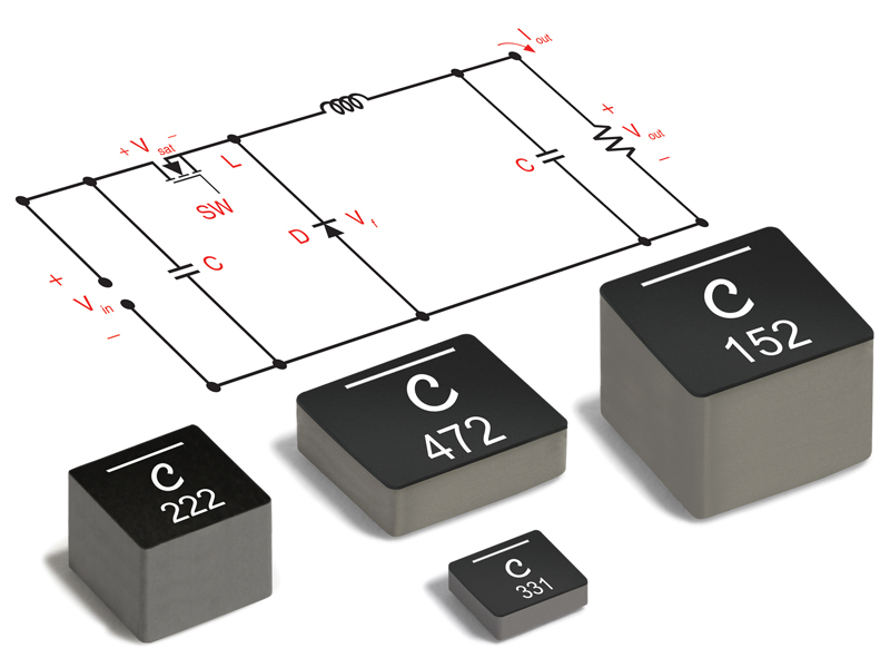
The choice of inductance value results from a variety of considerations in any specific converter design. Since it is generally assumed that large inductance values come with penalties in either losses or physical size, a designer generally sets out to identify the smallest inductance value that will perform all the required functions for the converter. A typical starting point is to select an inductance value by L = v/(di/dt) such that peak-peak ripple current di = 20%-40% of the load current. This has been a traditional starting point that still works, and for a variety of reasons. Keeping relatively low ripple current certainly limits ac losses in the inductor (and other places in the powertrain). By reducing the ripple current, the peak current is reduced for all components including switches and rectifiers, impacting both losses and component reliability. In addition to losses, inductance value and ripple current also determine whether a buck converter goes into discontinuous mode at light load conditions. In the other direction, too much inductance can impact transient response. A full discussion of all these choices is beyond the scope of this article, but suffice it to say we must consider impact of inductor choice well beyond the inductor datasheet numbers.
Consider a 4 MHz buck converter with the following specifications:
Vin = 12 v Vo = 3.3 v @ 10A
For such an application, we might consider an inductor such as XAL5020-161 (160 nH). With a continuous current rating of 18.8 Arms, the inductor has plenty of current handling capability and this inductance value yields a ripple current of slightly more than 40%, roughly equivalent to our rule-of-thumb starting point.
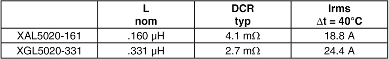
The datasheets indicate how much more efficient it would be to use an inductor from the lower DCR XGL family, but a clever designer will also notice that a higher inductance value can be had for the same or even less DCR. Inductor losses are proportional to DCR, but are exponentially related to peak-peak current, typically by a power of 2 or more. Hence, using higher inductance can save even more power than can just a reduction of DCR. In order to see this impact of reduced ripple current, we must go beyond the datasheet and use a tool that can evaluate total loss.
Click image to enlarge
Table 1: New inductors have lower DCR for higher L
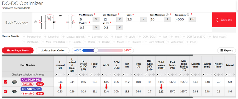
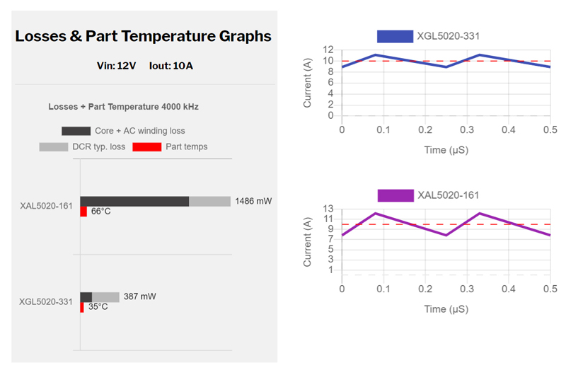
We can use the Coilcraft DC-DC Optimizer online tool to calculate a meaningful comparison of total loss for the selected XAL5020-161. The result shows that the low DCR XGL inductor lowers the total loss from over 1400 mW to less than 400 mW. The power loss saving of almost 75% greatly outpaces the DCR reduction which is on the order of 30%.
Click image to enlarge
Figure 3: New Inductance Choice Enhances Converter Performance
While DCR loss is certainly reduced, opting for .330 μH instead of .160 μH reduces the peak current from 12.2 A to 11.1A and the peak-peak ripple current of course by half, resulting in a major improvement in reduction of ac loss. The use of low DCR inductors to enable choice of higher inductance value has enabled a much more efficient solution while not increasing the inductor size.
Click image to enlarge
Figure 4: Advanced tools show inductor & converter performance beyond the datasheet
Summary
These examples demonstrate that important and dramatic innovations are occurring in the inductor industry, and how innovative thinking can fully utilize new inductors to optimize converter performance.