Author:
Jean-Loup Guédon - Senior Design Engineer at GAIA Converter
Date
02/20/2024
 PDF
PDF
Click image to enlarge
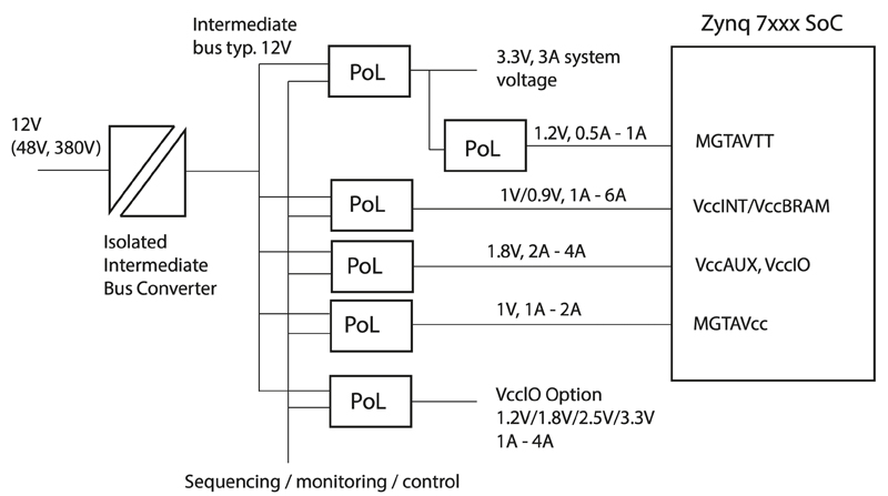
Figure 1: A typical distributed power architecture using an intermediate bus and point of load converters, here the load is a Xilinx SoC device
Even while accounting for DC power distribution, the disparity between input and output voltages gets larger, with supply rails often subject to wide variations, while the outputs, sometimes down to around 1V, must be ever-more accurate and disturbance-free.
Power conversion in a single stage with isolation from a wide-ranging input results in a compromise in efficiency and the arrangement is unable to provide multiple accurate outputs. Therefore, a common solution is to use an intermediate DC bus at typically 12V, 24V or 28V, generated by an Intermediate Bus Converter (IBC), followed by typically non-isolated high-efficiency Point of Load (PoL) converters. These are placed close to the loads for best voltage accuracy and lowest power dissipation in high-current connections. The IBC is usually isolated and converts a voltage from a wide input range to a fixed regulated or semi-regulated output. Figure 1 shows a typical arrangement.
Navigating the layers of design constraints
In the design of a high-performance intermediate bus system, there are many constraints and goals to consider such as:
● Dynamic characteristics of the input; nominal range, surges, spikes and dips
● Isolation requirements from supply to end-loads; practical and statutory considerations
● Provision of multiple outputs with their own static/dynamic characteristics and regulation requirements
● Overall efficiency target and apportioning of power losses between system elements
● Space and cost budget
At a high level, it might seem that these requirements could be met from discrete designs or an assembly of appropriate modules from various sources. However, this is not the full story, as a professional design, particularly in hi-rel applications, must also consider transient and fault conditions and how these propagate and affect system reliability and availability. Cooling provision in a constrained space can also be a major issue and can often only be addressed later in a design, when actual volume occupied and power dissipated is known. All these secondary considerations can have significant cost implications in hardware and system development time.
An example of a secondary effect which can have wide system implications is the transient and fault current that might occur on a PoL converter output. Transients naturally occur with capacitive loads on start-up and if they are significantly over the normal running current, the PoL and preceding IBC may need to be over-sized to avoid overload, stress and dips in the intermediate bus voltage, possibly affecting start-up of other PoLs. Similarly, shorts and unintentional overloads on the PoL outputs should not affect the intermediate bus if maximum availability of the system is necessary, with other PoLs maintaining their outputs, even if one is under faut conditions. In a hi-rel application, redundancy and monitoring might be included so that full functionality is retained even with a single PoL shorted.
Intermediate bus converters often need to be oversized
Putting some figures to the discussion, if a 5V PoL for example, has a nominal running output current of 5A, available parts might have a current limit as high as 16A, set internally. This represents perhaps a transient 60W of extra draw from the IBC as the limit is reached with a start-up surge, allowing for conversion efficiency. Other PoLs in the system will also contribute to start-up current surges so although the IBC may not be thermally stressed by the transient load, it must be capable of providing it without its output voltage dropping. It may therefore need to be rated for significantly higher than the nominal running power, adding to size and cost.
A solution is to choose PoLs with precision current limits that are just a little higher than the normal running current, so that surge and fault currents do not reflect back to the intermediate bus. PoLs with accurate current limits are however rare, as it is difficult to sense DC output current without unacceptable losses or high cost. A common compromise is to include a power rather than current limit for overloads and an overtemperature shutdown. However, the power limit is typically poorly controlled and the resulting current varies with input voltage, temperature and other circuit conditions.
If PoLs with precision current limits were available, parts would need to be chosen matched to the individual expected running current of each output. This would imply multiple types, possibly in different mechanical formats, each with their own unique heatsinking requirements. If discrete designs are considered, heatsinking becomes an even bigger challenge with a very variable skyline for the components typically used, particularly the inductor in the buck converter topology. Additionally, any future change to the normal running current would require sourcing and qualification of a new PoL and possibly even motherboard redesign.
A better solution with trimmable current limits
PoLs with controlled inrush, trimmable current limit and trimmable output voltage are the ideal future-proof solution and are available from GAIA Converter such as their MPGS14EB product. Along with reducing peak inrush current into capacitive loads, the MPGS14EB can be set to supply the designed running current with just a little extra margin so that short circuits do not reflect to high current on the intermediate bus. This ensures that other MPGS14EB parts are unaffected and maximum system availability is achieved, especially when redundancy and monitoring is incorporated. A common design of PoL module can be used with a voltage and current limit adjustable between the highest and lowest output requirements. Inevitably one or more PoLs could be running at lower than their maximum capability, but any premium paid is offset by savings in the cost and sizing of the intermediate bus converter. The use of the MPGS14EB also has the advantage of having identical PoLs, giving economy of scale and ease of heatsinking, with their common mechanical format. Development and qualification time is reduced with common PoLs and avoiding the cross-coupling effect of one shorted PoL affecting the bus and consequently other PoLs, could of course be invaluable in a hi-rel system.
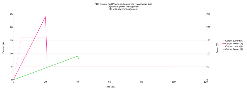
Figure 2 shows how the MPGS14EB from GAIA Converter controls peak current on start-up with a capacitive load, compared with PoLs without the function.
Click image to enlarge
Figure 2: Comparing peak start-up current for PoLs with and without controlled inrush current
Click image to enlarge
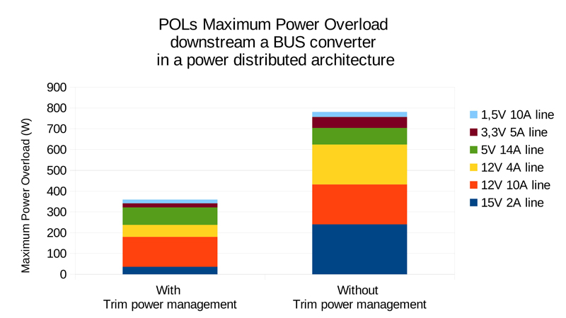
Figure 3: Example maximum fault loading on a bus converter with and without PoL trimmable current limit
Figure 3 shows how bus loading and IBC rating under overload conditions could be potentially halved in an example distributed power system with PoLs incorporating trimmable current limiting.
The GAIA Converter board-mount, through-pin MPGS14EB part, has a maximum capability of 260W, but has been designed to operate efficiently over a wide range of loads down to below 30W. Typical efficiency achieved is 97%. Output voltage is adjustable from 1.2V to 24V and current limit can be trimmed from 0 to 16A making it extremely versatile, matching a wide range of loads. The part also includes pins for sequencing control, synchronization and load current monitoring and parts can be paralleled with active load sharing. Input voltage range is ultra-wide at 4.75-36VDC (42V/100ms peak). Being a buck converter, the input voltage is always set higher than the output voltage.
Physically, the MPGS14EB is presented in a metallic case just 28 x 20 x 8mm with a top face suitable for connection to a heatsink or cold plate, which can conveniently span multiple devices. Thermal impedance is further lowered by use of high-performance resin encapsulation.
The bus converter can now be selected to optimize the system
The extremes of the input voltage range of the IBC, its optional output voltage and output loading range should be explored to find the ‘sweet spot’ where the combined efficiency of IBC and PoLs is highest. GAIA Converter offers regulated bus converters with a wide choice of power ratings from 10W to over 500W and with all common bus voltage outputs. Input ranges include 9-36V, 12-40V and ultra-wide 12-140V. An example distributed power system is shown in Figure 4 using the 500W GAIA MGDS500 IBC and five GAIA MPGS14EB PoLs.

Click image to enlarge
Figure 4: An example distributed power system using single PoL types from GAIA Converter with programmable current limits
Conclusion
Design of a distributed power architecture involves many choices and can be heavily constrained by the performance of point of load converters under transient load and short circuit conditions. By selecting PoLs with programmable current limits, the constraint is removed and the designer is more free to select an optimal and cost-efficient solution.


