IGCT device with extraordinary high SOA
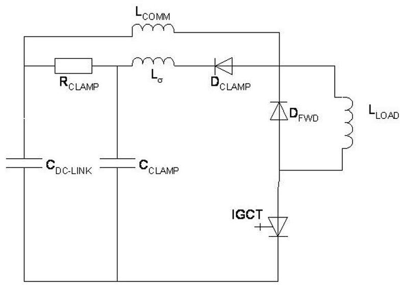
Figure1: The test circuit used for all turn-off measurements Lcomm= 3.2 μH?Configuration 1: Cclamp = 10 μF, Rclamp = 0.625 ?, L? = 330 nH?Configuration 2: Cclamp = 20 μF, Rclamp = 0.37 ?, L? = 325 nH
A 4.5 kV IGCT (Integrated Gate Commutated Thyristor) with extraordinary high Safe Operating Area (SOA) at 140°C is presented. The improvements for the IGCT were achieved by optimizing the corrugated p-base doping profiles of the original IGCT design. IGCT high power switches are considered overall to be the best choice among power semiconductor switches for high power applications such as medium voltage (MV) motor drives, interties and power-quality segments. This is due to its low losses, high load cycling, high power handling, and especially high current turn-off capabilities. With respect to the losses, an IGCT can be best described by the following statement: Turn-on losses for an IGCT are as low as those of a mechanical power switch, conduction losses are as low as those of a thyristor and turn-off losses are as low as those of a high voltage IGBT. The power ratings of converters are limited by the conduction losses and turn-off losses of the IGCT and the maximum junction temperature of the IGCT. On the other hand, the current turn-off capability (Safe Operating Area SOA) determines the power rating of converters. In line with recent trends in power electronics, operating the semiconductor device at a higher temperature enables a higher power rating of the converters. The IGCT was invented by ABB in 1997, and since its introduction to the market, the IGCT has established itself as a highly reliable switching device in more than 10'000 MV AC motor drives. Additional applications include full conversion wind mills (> 5 MW), marine drives for cruise ships and motor drives for the process industry. In comparison to the first IGCTs on the market, the latest HPT IGCT (see below) shows improved current handling capabilities in excess of 150%. Corrugated p-base in HPT IGCTs The introduction of the corrugated p-base to the IGCT design was a large step toward high current turn-off capability [1]. The corrugation is formed by two different Aluminum (Al) doping profiles: one underneath the cathode segments and a deeper profile between the segments. This led to the desired shaping of the current flow during turn-off: The current density beneath the finger is reduced and the current is more easily commutated to the gate. The biggest advantage of the corrugated p-base is increased SOA. A high SOA is needed for hard switching, snubberless AC motor drive applications, where switching between current state and voltage blocking state should be instantaneous. The corrugated base of the IGCT is referred to as "High Power Technology" (HPT) [1]. ABB Semiconductors has developed a full IGCT range based on this technology for voltage classes 4.5, 5.5, 6.5 kV and 10 kV. The HPT IGCT devices are well suited for serial connection to reach the required medium voltage level in 2-, 3- and multi-level topology configurations. Paralleling of devices is normally not required, because of the high current capabilities of the individual IGCTs. In order to reach even higher levels of power management with IGCT MV drives, the next generation of IGCTs must be rated at higher working temperatures while further improving SOA. Optimization of parameters for higher temperature operation The starting point for optimization is the current 4.5 kV HPT IGCT with the corrugated p-base. The conventional HPT corrugation and the new optimized one referred to here as HPT+ corrugation is formed by masked Al implantations and subsequent diffusion steps. The shape of the p-base has been varied. The parameters used to tailor the turn-off behaviour are:
- Junction depth and Al doping profile underneath the gate and cathode finger
- Width of the implantation mask, thus the width of the bulge
- Turn-off capability, especially multiple turn-off events at 10 kHz (burst) at high temperatures, e.g. 140°C. Testing multiple turn-off events at high temperature is critical because this test combines high temperature with switching losses and high turn-off currents
- Turn-off losses
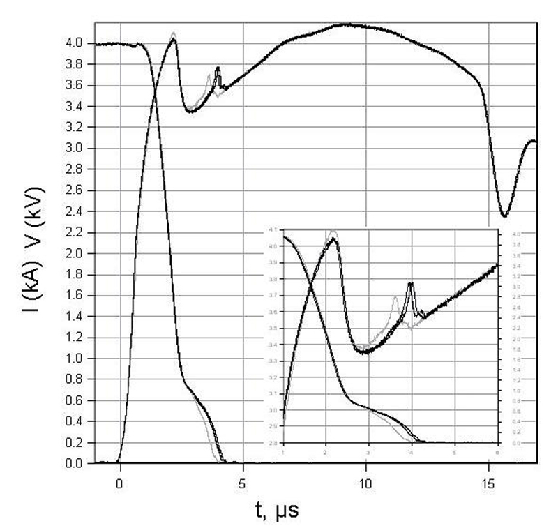
Leakage current and turn-off losses With an increased junction operating temperature, the leakage current and thus conduction losses increases. The 91 mm HPT+ IGCT under investigation has a leakage current < 10 mA at 3.2 kV and 140°C, and the leakage remains stable and low during long time testing at 3.2 kV and 140°C. The optimized p-base with HPT+ technology leads to reduced turn-off losses resulting in an improved technology curve. The losses are reduced by 0.8 Ws or ~4% at 125°C (4 kA against 2.8 kV, circuit configuration 1, Fig. 1). The turn-off waveforms at 125°C in Figure 2 show why the switching losses are lower with the optimized p-base. The main difference is the shorter duration of the tail current. The tail current is reduced by the interaction of the optimised p-base and the weaker anode.
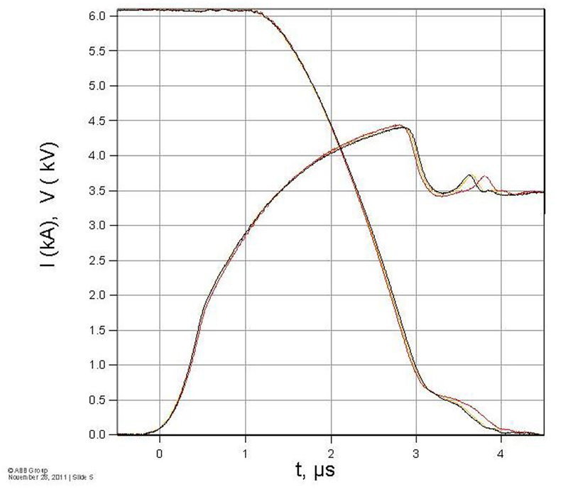
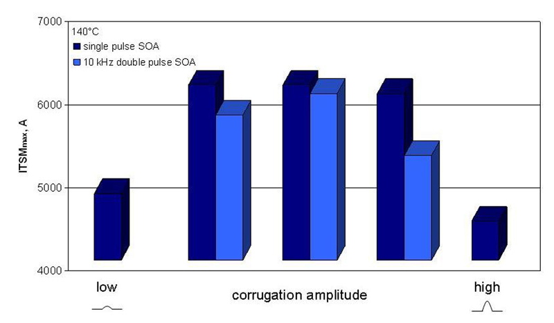
Turn-off SOA Capability The turn-off capability of the new HPT+ IGCT is very high. For two subsequent turn-off events with a frequency of 10 kHz, it reaches around 6.0 kA against 2.8 kV DC-link voltage. A turn-off waveform at 140°C is shown in Figure 3. A current of 6.1 kA is successfully turned off against a DC-link voltage of 2.8 kV. The p-base profiles have been tailored for the highest snubberless turn-off capability at 140°C in a 10 kHz double pulse test. Under these conditions, the optimized p-base corrugation leads to an SOA increase of approximately 800 A compared to the standard corrugation. Figure 4 shows the results of one part of the optimization experiment. In this experiment, the doping profile underneath the gate was kept constant while the corrugation amplitude was varied. Single turn-off SOA and double pulse SOA tests were carried out at 140°C. The test results show that there is an optimum corrugation amplitude where SOA is at its maximum. If the p-base profile is too flat (low amplitude), the desired shaping of the current distribution is lost. It has not yet been clarified why the SOA goes down if the p-base underneath the cathode segment is weaker (high amplitude). One possible explanation is the disadvantageous localized heat generation.
Conclusion In order to increase the maximum output power of high power converters, IGCTs with low losses and high turn-off capability at a high junction temperature are required. We have optimized the corrugated p-base doping profiles of the HPT IGCT in order to achieve these goals. For the resulting HPT+ IGCT design, the turn-off losses are reduced without compromising the turn-off overvoltage. Furthermore, the turn-off capability in a 10 kHz double pulse test at 140°C has been improved by 800A. www.abb.com