Author:
Chris Siegl and Aung Tu, Fairchild Semiconductor
Date
02/17/2014
 PDF
PDF
Advances in system level goals of the Smart Grid to better manage electrical loads during high demand time of use or during a shortage of available resources have created a need for efficient methods of connecting and disconnecting loads from the grid. Load management systems have been available in the commercial and industrial arena for some time. However, with the Smart Grid management systems now advancing on to the stage of controlling devices within the residential and commercial applications, the reliability, efficiency, and cost-effectiveness of such devices become more critical.
The connect/disconnect solutions must be tolerant of the noisy environment of the smart meter as it is directly connected to the incoming feed from the grid and controlled by a micro-controller. The best solutions combine strong DC current capability to open even welded shut contacts with accurate timing functions to filter out noise, relay protection, and the compatibility to optimize the micro-controller clock cycles.
This article reviews both the implementations currently in use and those in development.
Smart Grid system load management proposals, as well as switches needed in various emerging countries are also reviewed. Mechanical dual-coil relays are examined to define optimized driver circuits that provide the needed functionality.
The article concludes with a discussion of the power systems needed to drive the connection relay, as well as the driver trade-offs to meet the proposed performance specifications.
The Impact of Smart Grid
The Smart Grid initiatives have spawned new approaches in load management. The basic technology of remote controller and sequencing of loads in its basic forms has been a function of the industrial market for a long time with complex incentives for businesses to participate. Initially this was done largely through individual device wire telephone connections back to the utility as well as warning and request systems through a mechanism of telephone communications devices.
The cost of this has dropped dramatically with the introduction of wireless and Power Line Carrier (PLC) communication technologies and a healthy competition resulting in improved performance at constantly diminishing costs. Not being dependent on direct hardwire installation and intrinsic safety in the wireless implementations dramatically reduces the cost and complexity of the installation process.
The Residential Meter Market
Another inducement for an economical connect/disconnect requirement comes from the residential meter market. Enabled by the improvements in timely communications to individual meters and local control functions, the ability to remotely open a meter load greatly reduces service costs for a simple service stop or service restoration. There is no longer a need for a service truck when customers request service interruption and re-connects, such as for seasonally occupied vacation and rental properties.
Service personal interaction over non-bill payment issues is also minimized. Similar savings apply to temporary construction sites and other venues not needing continuous usage. This remote management capability also reduces power theft in these unoccupied sites and mitigates the associated power losses.
Mitigating meter socket failures
There have been concerns over recent instances of fires starting around newly installed smart meters in older meter sockets. When replacing older meters that have been in place for a long time, the issue has been traced to heating in the meter socket due to corrosion in the contacts to the meter. Heat buildup in the socket is a function of load current and level of corrosion, primarily caused by weather damage and water seepage. Disconnecting the load and reporting the over-temperature condition puts the meter in a position to mitigate the damage safely.
Disconnect after power is lost
Gaining in importance in contactors is the ability to disconnect and re-connect after power has been lost. This is especially important when controlling devices such as compressors, which have high start-up surge currents and are best not cycled without a minimum off time (compressors overheat if cycled over short intervals). Power restoration surges can be reduced by delayed turn on and sequencing of loads, thereby reducing peak surge currents and stresses on delivery equipment as well as loads.
Meter-based and load-based contactors can provide this function with capacitor stored holdup power which is sufficient to pulse the contactor open even in the power-loss event. Smart Grid research is showing significant advantages in equipment reliability and stability using these types of policies.
The Industrial Market
In the industrial market the contactor function has been implemented with a variety of approaches. Motors have been used to drive contactors but these suffer from slow speed during the opening operation with resulting arcing damage. For larger systems, various forms of arc suppression are often used including compressed gasses and spring assisted fast-switching mechanical implementations. These are not economical for the higher volume cost sensitive markets. Therefore the emerging consensus is to use a polarized bi-stable latching relay utilizing two coils with one coil pulsed to move the relay from the closed position to the open position and the second coil to move the relay from the open position to the closed position.
Detailed look at the Driver Configurations
The bi-stable, two coil latching relay is the most common configuration. Some versions include built in springs and other mechanical assistance in the open direction for lower-power operation.
The typical load connection function is implemented with a bi-stable contactor device with two or more poles to disconnect. The contactor is usually wound with two windings; one to close the contactor and the other to open the contactor. A permanent magnetic material or a mechanical latch is used to hold the contactor in place when it is not switching.
To facilitate the mechanical movement, the relay coils need to be energized for a specific time interval. Once the contact(s) have changed position, the voltage should be removed from the winding of the relay. A simplified, typical circuit diagram is shown in Figure 1 with example waveforms.

Click image to enlarge
Figure 1: Simplified Diagram of a Relay Drive
Relay Drive Circuit Requirements
As the diagram shows, a dual-coil relay is connected to its supply rail at the center point of the two relay windings. Each winding can be energized by the switches connected to the relay coils. The two switches must not be on at the same time, which would cause excessive currents to be drawn from the supply rail, and result in improper operation and damage to the relay.
To accommodate the relatively long time required for the relay contact to travel between its stationary positions (ON and OFF positions), the pulse must be longer than the minimum duration specified in the relay specification. It is also desirable to limit the maximum length of the drive pulse to prevent potential saturation of the relay winding and to avoid over heating the coils and drive electronics. The control signals should also be compatible with latest generation of micro-controllers supporting both CMOS and TTL input levels.
The relay specification also defines the minimum and maximum operating voltages for reliable operation of the contact(s). The voltage requirements of the contactor vary by application, which is driven by tradeoffs in meter requirements. Lower voltages are common in lower-cost low-power applications where the meter and the relay sizes are smaller. Higher voltages are common where higher currents are needed where the larger contacts require more power to switch. Therefore the drive circuit should monitor the relay bias voltage for sufficient voltage level. It is also desirable to have an under voltage lockout for the drive circuit to facilitate smooth startup while circuits initialize.
The preferred integrated solution provides input signal qualification for the control signals, protection against simultaneous activation of the two relay coils, a maximum drive pulse duration limit, and additional basic functions such as bias voltage monitoring, driver enable input, and thermal protection for the driver. The ideal circuit minimizes component count and board space, while increasing the reliability of the system and the noise immunity of the circuitry when driving the coils of the relay.
Practical implementation of power and connect/disconnect
Figure 2shows a block diagram of a typical metering system. The relay drive voltage is a function of the particular relay used. In general, larger current switching relays (larger contacts) require higher voltages to deliver enough energy to switch fast enough to minimize contact loss due to arching during the switching. Usually this high voltage source is provided by a capacitor to provide maximum power during switching especially in applications where switching occurs after power is lost.
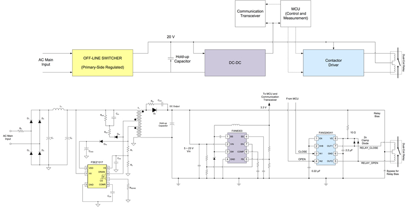
Click image to enlarge
Figure 2: a block diagram of a typical metering system
The capacitor has to be sized to provide the energy needed to switch successfully. The capacitor charging supply can be current limited, reducing the power supply cost by taking time to bring the switching voltage to full charge. The disconnect switching is an infrequent event in meters. The typical devices being switched, such as compressors, have a minimum required off time for long life operation. Longer recharge times reduce power supply cost and stresses without impacting performance.
Communications, control and measurement functions are typically implemented with low-voltage (3 to 5 volts) circuits such as micro-controllers and communications circuits. There are a variety of communications technologies that focus on particular market requirements and geographic constraints. Most of these have a burst profile where power consumption is on the order of 5-watt transmission for 100 milliseconds followed by a delay of one second or more before the next transmission. Transmission after power is lost (reporting the status of the network at the time of power loss) is also desirable for times of up to 10 minutes for last transmissions.
The holdup capacitor as described above for the disconnect function applies as well to the communications circuit if a DC-DC stage is included for efficient low- voltage conversion from the high-voltage capacitor. The holdup capacitor can now be shared by the transmission and disconnect functions if sized appropriately.
For a current-limited, off-line switcher supply, a primary side regulated flyback controller with an integrated MOSFET such as the FSEZ1317WA makes for a feature-rich economical solution.
The DC-DC block can be implemented with the minimal-parts-count high-performance solution such as the FAN8303, a step-down regulator with an integrated switch.
Finally, the connect/disconnect drive designed to meet the requirements as defined in this article can easily be implemented with the recently introduced FAN3240 and FAN3241 smart dual-coil relay drivers.
When Isolation is required
Sometimes isolation is required in cases such as when there is wire-line communications or where there are a number of circuits on different phases controlled from a common point. A relay driver such as the FAN3240 or the FAN3241 with a built-in bias supply can be very beneficial in reducing parts count and cost as well as circuit simplifications as shown in Figure 3.
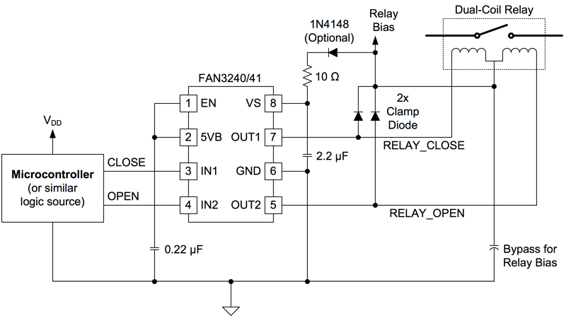
Click imag e to enlarge
Figure 3: A relay driver such as the FAN3240 or the FAN3241 with a built-in bias supply can be very beneficialConclusion
Variations on the presented solutions can be applied to other smart meter power requirements as well as distributed connect/disconnect functions in a variety of specific applications. As the Smart Grid functionality continues to expand in complexity, new opportunities will emerge for new power management functions. Fairchild Semiconductor has tools, application notes and application pages accessible through the Fairchildsemi.com web page to help you in your design process.