Optimizing Thermal-Management for Best Performance and Reliability
Efficiency is never 100%, even in the best systems
Power conversion is common to almost all electronic systems. Efficiency is critical, whether the objective is to maximize runtime for a small battery-powered device, reduce utility costs to power data-center servers, or others such as ensuring cost parity for renewables.
Efficiency is never 100%, even in the best systems. That small amount of un-transferred energy is converted to heat, which then presents reliability challenges. Without effective thermal management, heat-dissipating components like power transistors or resistors can run too hot – leading to early failure - or in extreme cases may exceed their maximum rated temperature resulting in rapid destruction.
Reliability follows the Arrhenius Law, which incentivizes cooling: reducing a component’s operating temperature by 10°C can double its lifetime. Moreover, taking steps to ensure a lower junction temperature can increase power capability and allow the power supply to operate safely across a wider ambient-temperature range.
The small proportion of power that enters the power transistors but is not transferred to the load is dissipated from the junction of each device. The junction temperature is related to this power dissipation by the equation:
Tjmax = (PDmax x Rθja) + Ta
Where Tjmax = maximum junction temperature
PDmax = maximum power dissipated
Rθja = thermal impedance from junction to ambient
Ta = ambient temperature
When designing a power supply, the objective is to design for a junction temperature that will not only preserve the device but also ensure the desired reliability. The maximum power dissipation can be estimated using the datasheet efficiency curves. Similarly, the thermal impedance, θja, from junction to ambient, can be found from datasheet curves that also consider cooling effects such as PCB metallization and airflow.
If an acceptable junction temperature cannot be achieved, when delivering the required power to the load, the design effort must focus on reducing θja. A variety of techniques can be used to achieve this. These include:
· Package selection, taking advantage of packages with enhanced internal features like thermally efficient clips to replace conventional wirebonds, or enlarged metallized areas on the lower or upper side of the die - or both sides for dual-side cooling; these areas are connected directly to a heat slug or exposed metal pad that can be soldered to PCB metallization or attached to a heatsink.
· Board design, including increasing the copper thickness, or adding thermal vias directly beneath the hot components connecting to a heat spreader such as a heavily metallized layer. An insulated metal substrate may also be considered if extremely high heat dissipation is needed.
· More overt thermal-management techniques, such as heatsinks or heat pipes, possibly in conjunction with a cooling fan.
The question arises as to which combination of these techniques should be used for optimum effectiveness, acceptable size and weight, and minimal impact on Bill Of Materials (BOM) cost. The answer is not always obvious, but the potential consequences of over- or under-engineering the solution are clear.
Building multiple prototypes to explore different thermal designs may not be viable. On the other hand, if the chosen solution is found to be unsuitable later in the project, redesigning the board to add extra thermal vias or to accept a different package style may be impractical.
Fortunately, help is at hand. Thermal simulation software can help engineers visualize thermal behavior from a system perspective and identify any problem areas before committing to a first prototype.
Some online tools are even available free of charge. TI’s WebTHERM is an example, which is ready to perform thermal analysis on a power supply design created using the WEBENCH online environment. The power supply is initially designed as a WEBENCH project, using the chosen controller or DC/DC converter IC and known requirements like power-supply input and output voltage ranges.
Once the basic design is completed, WEBENCH compiles the bill of materials and calculates parameters such as power dissipation and θja. These can be used to calculate Tjmax manually, using known ambient-temperature data. However, running a webTHERM simulation allows users to see the thermal performance graphically, and also shows secondary effects such as co-heating of components that can be difficult to visualize otherwise. The result of the simulation is a color temperature plot that helps quickly identify any areas of concern.
To run a simulation, the user enters settings like the load current, top and bottom ambient temperature, and device case temperature. A thermal simulation can be run in a few minutes, capturing results that can be analyzed graphically using the color temperature plot. If necessary, the design can be changed within WEBENCH to optimize the thermal performance, by changing the board size or copper characteristics on any of the layers, or adding and adjusting thermal vias.
Multiple simulations can be run and compared to identify a design that produces an acceptable temperature. If a suitable Tjmax cannot be assured, additional thermal management such as a heatsink or heat pipe to remove thermal energy from the system more quickly. The temperature plot can help focus attention on the areas of main concern.
Adding a Heatsink
A heatsink is easy to understand and extremely reliable, with no moving parts, no failure mode, and no operating cost. Usually aluminum, or copper, they can range from simple stamped metal wings intended to be applied to a single transistor, to milled or extruded parts with finning designed to intercept convection airflow for maximum heat transfer. Convection occurs naturally, as warmed air rises, which perpetuates the flow. Care must be taken to ensure unimpeded airflow from inlet to outlet, also making sure the inlet is placed below the level of the heatsink and the outlet above. This is necessary to prevent heated air stagnating above the hot component, which can exacerbate junction-temperature rise.
Despite their many advantages, heatsinks can become large, heavy and costly if sized to dissipate large quantities of heat. The constraints on positioning for best airflow may compromise board layout, and fins can become clogged with dust or dirt and so impede cooling. Attaching the heatsink properly to the component, with clips or screws and a layer of thermal interface material (TIM), also adds to assembly time.
A vast variety of heatsinks are available from manufacturers such as Aavid Thermalloy or Wakefield-Vette, including parts that are optimized to fit specific components, such as processors or FPGAs. On the other hand, heatsink selection can be based on calculations that consider its effect on reducing θja,the overall thermal impedance from the chip junction to the air surrounding the heatsink, resulting in lower junction temperature relative to power dissipation.
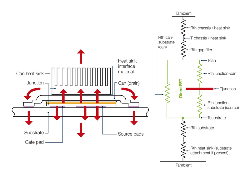
Figure 1 shows a power transistor in a thermally enhanced packaged designed for efficient dual-sided cooling using a top-mounted heatsink and a heat spreader in the PCB. The system is shown modeled as a network of thermal impedances, Rth, between the active junction and the ambient environment above and below the board. The thermal impedance of the heatsink, Rth heatsink, expresses how efficiently heat can be transferred from the base of the heatsink to the ambient environment.
Extend Design Freedom with a Heat Pipe
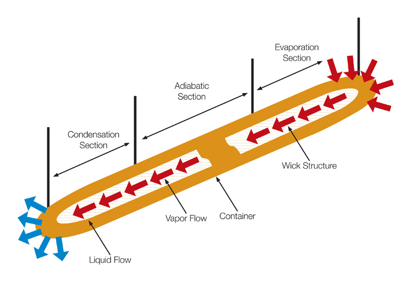
In some designs, constraints on overall size or board layout, or impeded airflow, may prevent attaching a heatsink of the required size directly to a converter IC or power transistor. A heat pipe (Figure 2) can offer a practical alternative, which enables heat to be moved from the source to another location where a suitable heatsink or spreader can be positioned, and greater airflow provided for cooling. The part illustrated, the Wakefield-Vette model 120231, can handle thermal loads up to 25W but is only 6mm diameter × 100mm long.
The heat pipe does not act as a heatsink itself but is a sealed tube designed to transfer heat from its hot end to the cool end by leveraging phase-change principles. Heat is absorbed at the hot end and vaporizes the working fluid inside the tube. The vapor travels towards the cool end and condenses back into liquid releasing its heat in the process. The liquid then travels back to the hot end of the pipe to repeat the sequence. Among the advantages of a heat pipe is that no power is required to sustain this phase-change mechanism, and the designer has the freedom to position the cool end of the heat pipe in the most suitable location.
Click image to enlarge
Figure 2: Heat pipes are available in various shapes and sizes, or can be customized, to transfer heat to a convenient place to be dissipated by a heatsink fan
Forced-Air Cooling
If passive thermal management using heatsinks or heat pipes is unable to achieve the desired junction temperature, forced-air cooling using a high-quality fan from a manufacturer such as Delta Electronics may be considered. A fan gives the flexibility to optimize cooling by selecting fan size and adjusting speed to increase or decrease the airflow, rated in cubic feet per meter (CFM).
Conclusion
Proper thermal management is essential to maximize both the performance and reliability of board-mounted power supplies or DC/DC converters. Designers have plenty of tools at their disposal, but it is essential to avoid over-engineering to prevent excessive bulk, BOM cost, or complex assembly challenges. Accurate thermal simulation tools are available free of charge, which provide a visual guide to thermal-management challenges before committing to building hardware. Other techniques such as a custom-selected heatsink, heat pipe, or cooling fan can help overcome broader system constraints on circuit layout or airflow.
Mouser Electronics