Output Filter Capacitor Characteristics and Performance in Miniature Switched-Mode Power Supplies
Switched-mode power supplies (SMPS) offer size, weight, and efficiency advantages ideal for meeting the end system goals for a wide range of applications
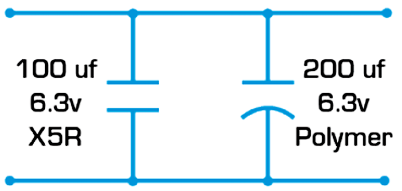
Figure 1: A typical schematic for output filter capacitors
Switched-mode power supplies can introduce conducted or radiated noise into a system, which is a potentially significant disadvantage.
Noise control is increasingly achieved with streamlined designs that use of one or two chipsets, have matched performance, and are designed to provide simple, proven integration and performance. Other methods include impedance matching, minimizing physical traces, and employing efficient filtering throughout the design.
Multilayer ceramic capacitors (MLCCs) are often used for high-frequency noise filtering and bulk capacitors are often used for low-frequency filtering and high-current hold up functions.
Recent advances in MLCC technologies have achieved higher capacitance per unit volume (high CV) and garnered increasing acceptance of new three terminal high-CV MLCC filters. Stacked bulk capacitor use also continues to expand.
These advances have expanded the intersection of applications that MLCCs, tantalum polymer, and aluminum polymer capacitors are ideally suited for.
High-CV MLCCs
Modern MLCCs offer designers a high-capacitance alternative to traditional electrolytic capacitors in a small form factor. Material advances, improved electrode and dielectric thickness control, and enhanced processing procedures advances have combined to achieve small, high-CV MLCCs. The same technology that enables 100µF, 6.3V 0805 X5R MLCCs also enables ultraminiature 100nF 008004 MLCCs.
Click image to enlarge
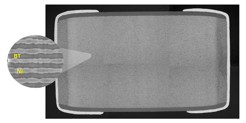
Figure 2: A cross sectional view of a high-CV 22µF 0402 MLCC with 500 dielectric layers, each of which is less than 1/100th the thickness of a human hair
Designers are typically aware of the temperature and aging effects of high-CV MLCCs, but they often overlook the DC voltage bias effects, which can be significant and can vary greatly by case size and manufacturer.
Click image to enlarge
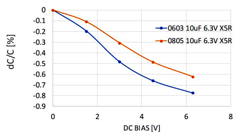
Figure 3: A comparison of the typical capacitance loss and DC voltage bias for a 10µF, 6.3V, 0603 X5R MLCC and a 10µF, 6.3V, 0805 X5R MLCC
Stacked MLCCs
Stacked MLCCs offer lower inductance and ESR than other bulk capacitor technologies and, as such, are increasingly employed in medium- and high-power SMPS. They also offer higher reliability than wet aluminum electrolytic capacitors.
Click image to enlarge
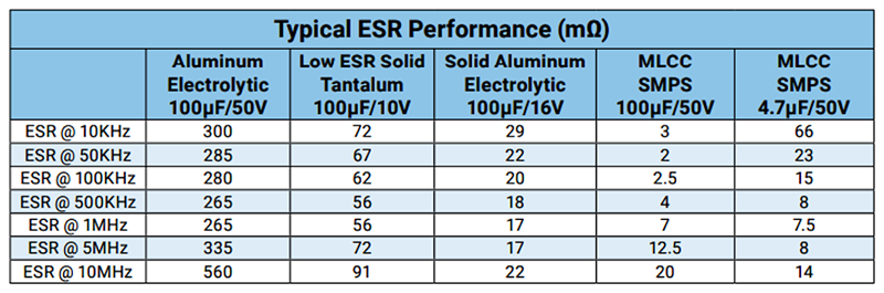
Figure 4: Typical ESR performance for bulk capacitor technologies. Stacked MLCCs are represented in the second to last column
Three Terminal High-CV MLCC Filters
Three terminal high-CV MLCCs are essentially just MLCCs that use nonferrous materials to form an LC (T) EMI filter that acts like a broadband notch filter and exhibits low Q, low parallel inductance, maximized series inductance, and high current capacity in a small case size. Many of these components can handle steady-state currents of 2A and beyond, including 15µF 0402 variants, which are pretty common.
Click image to enlarge
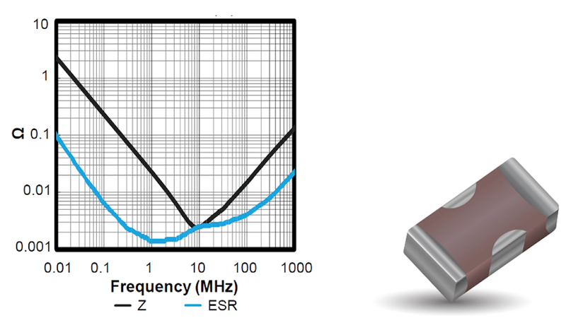
Figure 5: Impedance and ESR versus frequency performance (left) for a 15µF, 4VDC 0402 three terminal high-CV MLCC filter (right)
These multifunctional single-component solutions improve PCB space utilization and eliminate many of the solder connections associated with multiple component solutions in complex filters, which also improves reliability. However, like high-CV MLCCs and stacked MLCCs, DC and AC bias, aging, and temperature effects have the potential to negatively affect their capacitance value stability. Class 1 MLCCs don’t experience these instabilities, but Class 2 MLCCs can experience up to a 90% reduction in capacitance, so it’s important to consider other solutions.
Non-MLCC bulk filter capacitors, including conductive polymer, aluminum polymer, and tantalum polymer capacitors, have made tremendous technical progress in recent years. By responding to demands from high-volume end users across the spectrum of electronics, passive component manufacturers have significantly increased their performance and its impact on ripple currents.
Conductive Polymer Capacitors
Conductive polymer capacitors offer multiple advantages. They exhibit significantly reduced ESR, which allows them to handle higher currents with less heating, improve performance reliability, and enable benign failure modes. For example, failure sites resulting from manufacturing defects or end use misapplications will experience heating, but in conductive polymer capacitors, that heating transforms and isolates the failure site by instigating a cathode peel off that effectively isolates the failure and eliminates the possibility of catastrophic failures.
The most prevalent options for low- and medium-output bulk capacitors are based on aluminum electrolytic or tantalum technologies since both offer conductive technology counterparts.
Aluminum Polymer Capacitors
Aluminum conductive polymer capacitors come in layered and wound styles.
Layered aluminum polymer capacitors have a conductive polymer electrolyte with a stacked electrode structure. Layered versions tend to have resin compound cases equipped with J leads and offer reduced inductance over wound versions, which further extends their frequency response. They also have significantly reduced height profiles relative to wound versions, and lower profile cases exhibit better shock and vibration performance and support ease of implementation in space-constrained designs.
Wound aluminum polymer capacitorsare also based on conductive polymer electrolytes, but they have a wound rather than a stacked electrode structure. They also have a higher capacitance range and exhibit lower ESR than layered versions.
Click image to enlarge
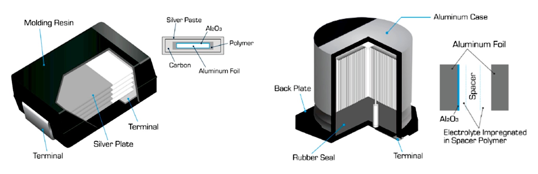
Figure 6: Structural diagrams of stacked and wound aluminum conductive polymer capacitors
Tantalum Polymer Capacitors
Tantalum conductive polymer capacitors feature a conductive polymer in the cathode and are formed by capping the tantalum anode wire with a porous pellet of tantalum powder, sintering that structure into a monolithic block to form a Ta2O5 dielectric, depositing a conductive polymer layer onto the monolithic block structure to reduce ESR, and completing some added processing.
These miniature bulk capacitors are available in a variety of voltages, case sizes, height profiles, and quality levels. Currently, tantalum conductive polymer case sizes can range from 0402 to 2924 with height profiles as low as 0.55mm, part volumes as low as 0.363mm3, andweights as low as 1mg. This broad range of form factors allows designers to place these capacitors at ideal PCB locations for maximum efficiency.
Tantalum polymer capacitors exhibit ESL as low as 1nH and very low ESR — typically just one eighth the ESR of standard MnO2 tantalum capacitors — and can therefore handle much higher ripple currents. They also exhibit improved energy density, and virtually no aging, voltage bias, or temperature instability effects.
Click image to enlarge
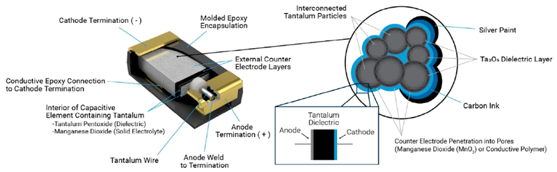
Figure 7: A cross sectional structural diagram of a tantalum conductive polymer capacitor
Conductive Polymer Bulk Capacitor Application Test
A customer had a delivery issue with aluminum polymer capacitors and wanted to substitute a tantalum polymer capacitor if circuit testing confirmed the suitability of the substitution.
Click image to enlarge
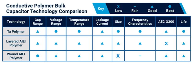
Figure 8: A general comparison of tantalum, layered aluminum, and wound aluminum conductive polymer capacitors
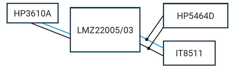
Per the customer’s request, we selected an LMZ22005 evaluation board to evaluate the impact of the two conductive polymer output capacitor technologies on ripple current and drove the evaluation board at 9V on the input, which was comfortably within the board’s input voltage range of 6V to 20V. The output voltage we selected for this study was 3V.
We conducted two test cases with aluminum conductive polymer and tantalum conductive polymer bulk output capacitors rated for 220µF, 15mΩ, and 6.3V and arranged in parallel with a 100µF X5R MLCC, which unsurprisingly dominated the ESR of the parallel combination. We also electronically loaded the circuit with an ITECH IT8511DC on the output terminals and measured similar ripple voltages with an HP5464D. As expected, the capacitors performed nearly identically, and we determined that the aluminum and tantalum polymer technologies were interchangeable in the customer’s application.
Click image to enlarge
Figure 9: The test configuration for the conductive polymer bulk capacitor application test
Conclusion
The testing proved that tantalum conductive polymer capacitors can effectively compete with and provide suitable replacements for aluminum conductive polymer capacitors in bulk output filter applications. They offer designers multiple advantages — ranging from ease of use resulting from a wide variety of case sizes, height profiles, and under-tab lead frame options to long-term stability and exceptional reliability — and are ideal for size- and weight-sensitive applications, including SMPS, microcontrollers, microprocessors, and FPGA.