Author:
Alexander Mezin, Sr. Field Application Engineer EMEA at SL Power Electronics
Date
12/24/2021
 PDF
PDF
Click image to enlarge
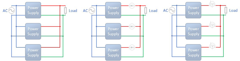
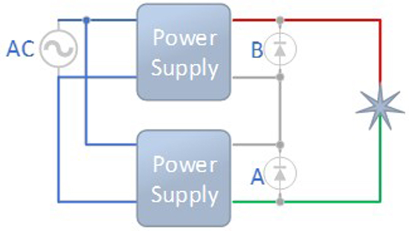
Figure 1: Redundant operation, basic star wiring options
A single power supply is most of the time sufficient in applications connected to an AC power source. However, there are sometimes additional boundaries set to fulfill either higher power needs, system reliability, or even mechanical constraints. The connection of two or more power supplies for redundancy is important in critical applications, where the power source fails cannot be tolerated. The current sharing circuit or, load sharing circuit, is the ability to manage the output current evenly across all active power supplies to greatly reduce stresses on each power supply and allow them to run cooler which results in higher reliability of the active power supplies.
A redundant sharing is the control of the power supplies internally or externally by switching only the desired number of the power supplies in parallel at the same time. In case of a power failure, the control circuit will automatically switch to another redundant power supply for continuous power delivery. Active redundant configuration allows to keep some of the connected power supplies in parallel not loaded and so the critical components are not stressed. Such a system approach extends the lifetime of the spare power supplies.
A typical selection of the power supplies for redundancy requires choosing the same type of power supplies connected in parallel to ensure identical operation no matter which unit will be connected to the load.
Although there may be more than one way to wire load sharing with parallel power supplies, the star wiring method is typically the one most recommended. Figure 1 shows the three typical star wiring schemes that provide options for any desired level of redundancy:
This first method in figure 1 left demonstrates a basic star wiring scheme that offers a basic level of redundancy without the inclusion of extra components that are not strictly necessary for a load-sharing function. However, many safety-critical systems demand reliability that evolves an advanced redundancy that requires additional components to this load share wiring scheme as shown in figure 1 middle.
Although OR-ing diodes are a successful and redundant method in their simplicity, they may be neglected for their power losses impact. This level of redundancy is still achievable without the impact of such power losses as figure 1 right exemplifies. This elaborate scheme consists of the same basic OR-ing star wiring method however, it is considerably more efficient. It demonstrates the introduction of a relevant OR-ing system with the use of MOSFETs driven by a compatible integrated circuit controller.
Higher current (parallel operation)
The reasons for the connection of several power supplies in parallel instead of using higher power units can be for example modular configurations or a variety of applications in a design house with an extended wider power range, mechanical limitations, or even lack of products in the market with the desired specification. A common example in modular applications is when the system designer adds more and more power supplies in parallel as the system building blocks are added. In a wide variety of scenarios, the purchasing team might prefer to have one single power supply on their bill of materials in simple designs and stacked power supplies in parallel from the same type in more powerful ones.
The selection requirements of power supplies in parallel operation are similar to those for redundancy, but the control function differs. As a single unit is not sufficient to provide desired power needs, two or more power supplies in parallel are expected to be always loaded. The control circuit responsibility shifts here to balancing the load sharing among the connected power supplies equally as possible.
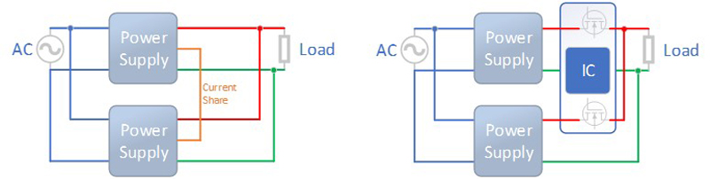
The balancing circuitry implementation can be achieved both internally in the power supply or also with external control units. An example for internal control implementation would be an additional load-sharing IC such as UCC29002 from TI. Power supplies in parallel with internal control will require an additional current share signal line for this method as shown in figure 2 left. External sharing control, such for example offered by Analog Devices LTC4370, is achieved by modulating the MOSFET voltage drops to offset the mismatch in the supply voltages (figure 2 right). This circuitry allows usage of any power supplies in parallel and takes the balancing control on additional independent PCB.
Click image to enlarge
Figure 2: parallel operation, internal (left) and external (right) current share control
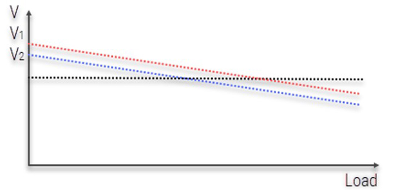
In applications, where the output voltage drop is allowed to be tolerated, the droop share method can be used. A basic understanding of such configuration is when the power supplies are designed to decrease the output voltage with increased load current. This allows two or more power supplies to “meet” with increased load current at the same voltage level and provide the power in parallel as seen in figure 3. V1 and V2 power supplies are identical but due to manufacturing tolerances often slightly differ in the output voltage. V1 has a higher output voltage and will be the first to support the load. With increasing current and so decreasing voltage V1, it will meet at some point the V2 level and start sharing the load between two (or more) power sources.
Click image to enlarge
Figure 3: parallel operation, droop current share method
The key points to consider for parallel operation of the power supplies are:
Click image to enlarge
Figure 4: series operation, basic wiring
Higher Voltage (series operation)
A somewhat easier technique to increase the total power is to connect the power supplies in series. The assumption is, that there are power supplies with lower voltage available to achieve the desired output voltage by stacking multiple power supplies in series. The output voltage of the overwhelming majority of power supplies available on the market is lower 60Vdc. System designs with voltage requirements higher 60Vdc might want to grip to this type of solution.
The main considerations for power supplies connected in series are listed below:
Click image to enlarge
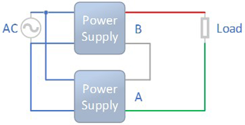
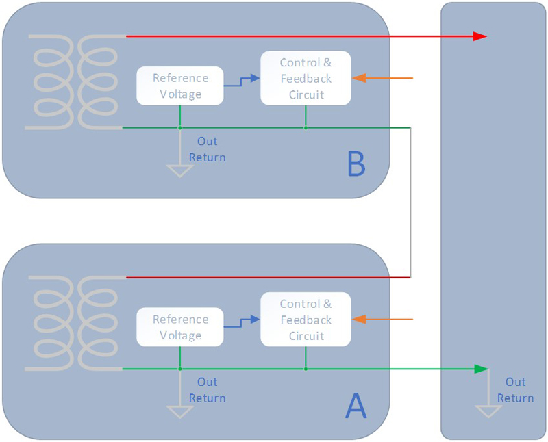
Figure 5: The reference voltage of power supply A shares the same signal ground as of the load. The signal ground of power supply B is elevated to the output voltage potential of power supply A
Click image to enlarge
Figure 6: series operation, reverse bias diodes protection