Promotes programmable power-conversion systems
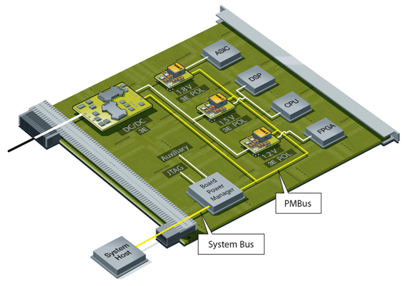
Figure 1: In a typical rack, the system host provides overall control for each board's power system via a Board Power Manager.
Digitally controlled power converters that embody power management subsystems and PMBus communications in telecoms applications makes it easy to assemble sophisticated hardware that suits a variety of distributed power applications. The ability to monitor the status of a power domain and fine-tune its configuration in real time lays the foundation for energy-saving schemes that will be especially attractive in systems that experience large load swings, such as datacom and telecom centers. A PC-compatible package, with its graphical user interface, extends ease-of-use to the software development realm, freeing users to experiment with alternative power-converter configurations. With its low-cost SMBus physical hardware layer and a standard command set that specifically addresses the power-conversion environment, PMBus™ provides system architects with a simple, robust and highly flexible platform that seamlessly communicates with any compatible power-system component - from AC-DC front-ends to variable-speed cooling fans. While many legacy components can only report rudimentary status information, fully exploiting the opportunities made available by the PMBus requires the intermediate-bus and point-of-load converters, which deliver load currents in a typical intermediate-bus-architecture (IBA), to include comprehensively capable measurement and control subsystems. Mostly built using mixed-signal silicon processes, today's digitally controlled power converters embody these additional hardware elements alongside the core PWM controller at negligible additional cost. As a result, system architects can construct sophisticated hardware schemes with unprecedented ease - the major challenge now being to develop supervisory and control software that maximizes system reliability and energy efficiency. Such schemes require the ability to reconfigure the power converters �on-the-fly', but crucially for more modest applications, PMBus mandates a �set-&-forget' mode where the converter behaves much like any other programmable component. This allows, for instance, one programming step to write its non-volatile memory with user-defined parameters, such as output voltage and current-limit values, in addition to any power-rail sequencing delays required by multi-rail logic components. Clearly, practicality and simplicity are key factors in the PMBus' success. Mirroring V2 of the SMBus specification, the bus comprises the clock and data lines SMBCLK and SMBDAT, which facilitate bidirectional communications between a bus master that initiates data transfer and the slave that responds when it recognizes its unique 7-bit address. PMBus adds two signal lines whose use is optional: SMBALERT#, an interrupt line to inform the system host that a device requires service; and CONTROL, which turns devices on and off in conjunction with PMBus commands. Electrically similar to I2C, a PMBus link is almost always confined to a single board. It may optionally communicate with other boards using the backplane-level system bus that uses the system designer's choice of network technology. Figure 1 shows the structure of a rack-mount board in a typical IBA environment, where local board power-manager logic most often forms a physical bridge between the onboard PMBus link and the backplane's system bus. The system host, which handles overall power control and management tasks, is the primary node on the system bus. The host could be an embedded system and/or external intelligence, such as a PC that might usefully link into the local enterprise network. Depending upon the degree of autonomy that the designer considers appropriate for individual boards, the board power manager might range from a simple bridge built using some leftover gates in an FPGA to a microcontroller with on-chip protocol conversion.
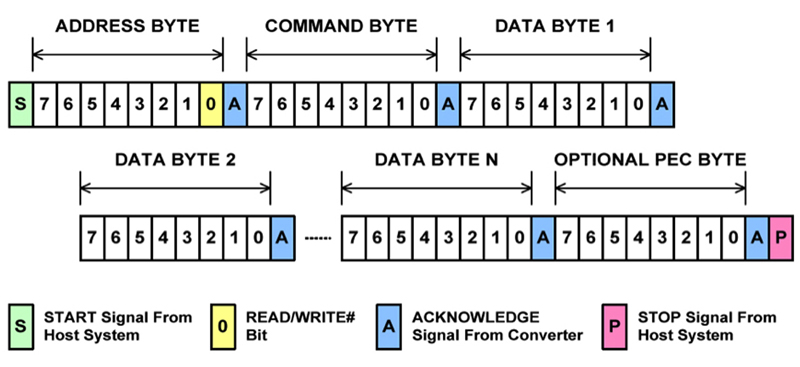
Standard command language eases programming Experience with long-standing communications protocols such as the test-&-measurement industry's IEEE-488.2 and SCPI (standard commands for programmable instrumentation) demonstrates that a well-developed standard command language is hugely influential in winning over designers wishing to simplify, secure and future-proof their projects. Again, the key is simplicity without compromising flexibility. The full list of standard commands appears in Part Two - Command Language - of the PMBus Power System Management Protocol Specification. With the exception of the last two codes, 0xFE and 0xFF, which form the first byte of a pair of two-byte extended-functionality commands, PMBus commands are single-byte entities. Accordingly, the format allows for 256 commands, each of which falls broadly into one of these categories: control, output, fault-limit, fault-response and time-setting commands; read-only status, monitor and identification commands; group and supervisory commands; and device- and manufacturer-specific commands. The great majority of the underlying functions within these groups are self-explanatory and generally applicable, such as setting power on/off delays and ramp times to implement power-rail sequencing without requiring any external hardware. But among the normal device-specific functions such as trimming calibration data, the last of these groups makes it possible to program aspects of the target hardware that are unique to a particular device. Such abilities may include altering the PID (proportional, integral and derivative) filter constants that control a digital converter's dynamic responses, or varying the dead-time period between the control and sync FETs switching in a buck converter to minimize losses with changing line-&-load conditions. Given suitable hardware, these capabilities are almost invariably new and offer the possibility of dynamically fine-tuning a converter's responses to suit its current set of operating conditions. At a higher level of control, established techniques such as dynamic bus voltage control that require extensive support circuitry in analog power converters become easy to implement when using PMBus-compatible digital converters. This energy-saving scheme involves intelligently reducing the intermediate-bus voltage when load currents are relatively small, which minimizes down-conversion losses in the multiple point-of-load converters that regulate the load voltages. As the load current level rises, supervisory software commands the intermediate-bus converter to increase its output voltage to ensure sufficient headroom for the point-of-load converters. This approach particularly suits systems that experience large swings in load current levels, such as those systems that handle networks and typically are highly dependent on traffic demand. These types of systems will often shutdown entire circuit blocks to save energy, when demand is low. PMBus greatly simplifies implementing the power control aspect of these systems. Evaluation kits ease hardware and software design The message-exchange mechanism that PMBus uses generally consists of a �start—target device address—command—data—stop' sequence. The number of data bytes that follow any command depends on the nature of the current exchange, with receiving devices asserting an acknowledge signal for every transferred byte. The sequence can optionally terminate with a PEC (packet error checking) byte as Figure 2 shows.
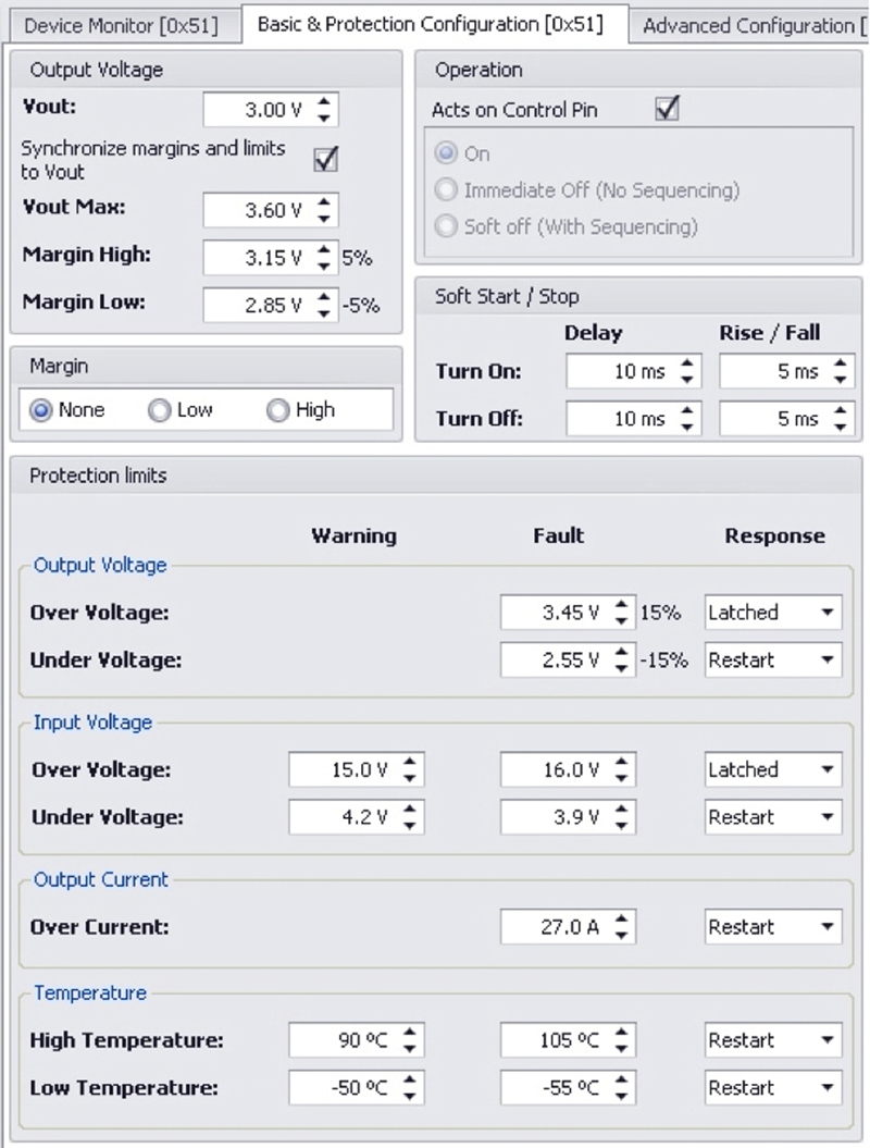
In the end system, dedicated hardware assumes responsibility for these exchanges, leaving developers to find a way of communicating with prototype hardware and evaluating alternative power-converter configurations. One approach that is proving popular uses a Windows PC to host a graphical development environment that communicates with an evaluation board via a USB-to-PMBus adapter. The evaluation board accommodates a selection of PMBus-compatible intermediate-bus converters and point-of-load regulators that designers can choose to closely replicate their target environment, while the graphical development environment vastly simplifies device set-up as the example panel in Figure 3 shows.
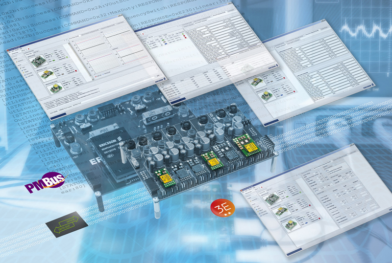
This example environment from 3E GUI Gold Edition specifically suits Ericsson's 3E family of digital intermediate-bus converters and point-of-load regulators, but unusually, it is also capable of communicating with any PMBus-compatible device. Furthermore, its facilities include a PMBus transaction log that records and analyzes message exchanges to speed troubleshooting. www.ericsson.com/powermodules