Designers and facility managers continue to find new ways to reap the benefits of using PoE
Power-over-Ethernet (PoE) is a technology used in wired Ethernet local area networks (LANs) that delivers power over the same cable that delivers the Ethernet data. This reduces the number of cables that must be laid to install a network and power the devices connected to it. It also makes it easier to maintain and adjust the access ports on the network to meet changing requirements than with traditional wiring. The PoE standard was originally developed to meet the needs of IT services and is appropriate for a wide range of network connected devices including IP telephony, IP security cameras, wireless access points, modems, switches, and other networked products.
Designers and facility managers continue to find new ways to reap the benefits of using PoE networks by connecting devices that were previously never associated with networks such as LED lighting. The nature of LED lighting lends itself to naturally leverage the strengths of a PoE installation. Before we explore how and why LED lighting and PoE networks are a perfect match for each other, we will go over the elements that make up a PoE network installation.
PoE defined
PoE technology is regulated by the IEEE 802.3 standard. The original PoE standard was released in 2003 and updated in 2009. It specifies that power and communication data be delivered across a single standard network cable wire (i.e., cat 5) directly to the RJ45 network port of the connected devices. PoE supports 10BASE-T, 100BASE-TX, and 1000BASE-T networks.
The power sourcing equipment (PSE) located in an endspan at the switch/hub, or used in a midspan, provide power to a connected device on the network referred to as a powered device (PD). An endspan PSE is an Ethernet switch that includes power within the network cabling. A midspan PSE is a power injector that resides between a normal Ethernet switch and the PD, and it injects power within the network cabling without affecting the data. Being able to install PSEs in midspan and endspan configurations supports legacy networks and offers more control over which network segments are powered.
In a PoE midspan insertion implementation, the PSE uses pairs 4-5 and 7-8 for power distribution. Power is distributed directly through the unused pairs in a midspan configuration for 10/100Mbps Ethernet (see Figure 1). The positive PSE output (V+) is connected to wires 4 and 5, while the negative PSE output (V-) is connected to wires 7 and 8. In this configuration, the power pairs are separated from the original signal pairs, which pass through the PoE midspan power injector. The midspan power injector is useful in installations where there is already an Internet connection and it is too expensive to change out or upgrade the Internet switch/router to provide PoE.
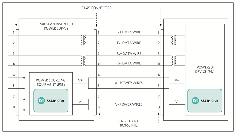
Click image to enlarge
Figure 1: PoE midspan insertion schematic for 10/100Mbps Ethernet
In a PoE endpoint insertion implementation, the PSE uses pairs 1-2 and 3-6 for power distribution (see Figure 2). The power in an endpoint configuration is supplied as a common-mode bias (DC) on the cable pairs, while Ethernet data is transformer coupled and fully differential (AC). In this configuration, the power and data share the same pairs of cable. The polarity of the PSE outputs is not defined for endpoint applications. In endpoint configuration, the Ethernet Magnetics are specially designed to withstand the DC bias resulting from the power.
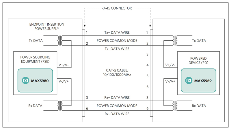
Click image to enlarge
Figure 2: PoE Endpoint insertion schematic for 10/1000Mbps Ethernet
Managing legacies
To support legacy installations, the PSE can supply power over two pairs of wires, at a maximum of 15.4W over a voltage range of 44VDC to 57VDC using cat 3 or better cabling. The standard also specifies that the PSE can supply 30W (over two pairs) or 60W (over four pairs) over a 50VDC to 57VDC voltage range using cat 5 or better cabling. For these three power scenarios, the PD is limited to a maximum power draw of 12.95W, 25.5W, or 51W respectively (to account for worst-case power loss in the cable) – all over a 37VDC to 57VDC voltage range.
The PoE standard is specified to avoid degrading data communication performance and protect the network equipment from overload through negotiation of power consumption between the PSE and the PD. The standard specifies how a PSE detects a PD when it is added or removed from the network, as well as, how to scale the supply current from the PSE.
The PD negotiates a power class with the PSE during its initial connection. All PDs include a 25kΩ resistor across powered pairs to allow the PSE to detect when a PD connects and disconnects from the network. To support legacy installations, newer PSEs must be able to properly power PDs on both cat 3 and cat 5 cabling. Likewise, a PD needs to be able to detect what type of power scheme the PSE can deliver to it. The selected power scheme is based on the highest compatibility between the PSE and the PD. Power is only delivered to compatible devices and is blocked to incompatible legacy devices. This allows users to freely and safely mix legacy and PoE-compatible devices on their network.
A perfect match
LED lighting is a near mainstream technology that delivers competitive cost and energy efficiency benefits versus other lighting technologies especially incandescent and halogen lighting. LEDs operate on DC power. A PoE PSE delivers DC power directly to the PD. Using an LED lighting PD on a PoE network delivers even better energy efficiency because it minimizes inefficient power-conversion stages for LED lights used instead in a retrofitted, legacy, AC power socket.
Powering and controlling LED lights over a PoE network creates the opportunity to use the LED lights in new and novel ways. For example, with appropriate battery backup or emergency power generation that is already part of the network installation; PoE-based LED lighting can be instantly repurposed and used to provide important lighting during a power outage without the need for a specialized, secondary lighting system.
The LED lighting can be used for more than just emergency lighting. It can also be used to communicate important and possibly dynamically changing information to building occupants, such as to show the safe exit paths out of the building, or indicate areas of the building to avoid if the LED lighting can be commanded to change color by an LED controller already installed in the PoE network.
Sensor integration
It is natural to couple an LED light with a sensor and a controller so that the LED light can adjust its brightness and color to provide a consistent lighting environment as the ambient lighting changes throughout the day. This type of lighting adjustment enables an LED light to smartly “harvest” sunlight more effectively than other lighting technologies can. However, once you have accepted the cost of a sensor and a controller integrated with the LED light, it is a small marginal cost to add additional sensors and modules to the assembly.
Installing smart LED lights in a PoE network creates new ways to interact with the building for facility managers and occupants. For example, facility managers can use the smart LED lighting system as an information collection network that enables historical and trend analysis to know how to better adjust temperature, ventilation, lighting, and cleaning schedules based on how occupants actually behave.
Occupants can also use the smart LED lighting system to access other building services like proximity sensors to discover the closest available meeting room. Items with RFID tags can be tracked if the smart LEDs include modules for activating and detecting the tags. Smart LEDS with wireless access points can be used to set-up short-range wireless networks.
The perfect fit with PoE makes it the future for LED lighting. PoE enables LED lighting networks to use a power supply that operates alongside a building’s legacy power infrastructure without having to address the many technical challenges associated with the variety of possible power infrastructures. Possibly the largest benefit of installing smart LED lights in a PoE network is that it provides a form of future proofing because the lighting, power-, and data-wiring is already installed where people need to be.
Scalability
Adding a new sensor or module to the smart LED hub is a low-cost way to add new capabilities to the existing infrastructure without an expensive lighting replacement. As the capabilities on the Internet-of-Things (IoT) continue to emerge and mature, the benefits of being able to quickly implement those “must-have” capabilities will accrue to those facilities that are using flexible, future-proofed installations such as LED lighting on a PoE network.