Author:
Anvin Joe Manadan, Senior Electrical Engineer, Inventus Power
Date
09/28/2020
 PDF
PDF
Click image to enlarge
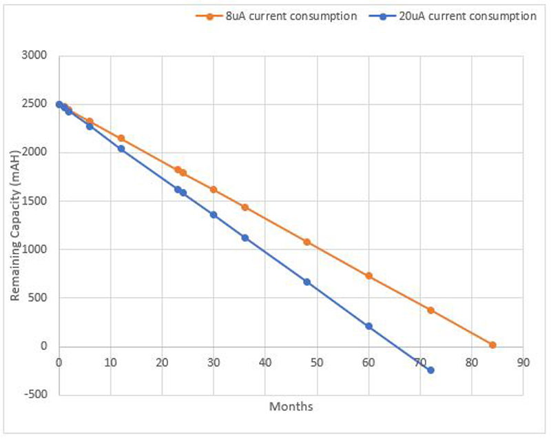
Figure 1: Storage life comparison for two battery packs with different power consumption
Batteries play an important role in our day-to-day lives in powering devices that range from TV remotes to heart pumps. Conventional batteries included only the cells, but high energy capacity Li-ion batteries also include electronics that are required to keep the battery safe and often includes a user interface to provide information on the battery status. These electronics require power to operate and consumes power from the battery itself which eventually reduces the energy available for the device that the battery is powering. This reduction in energy must be minimized in order to maximize the operational run time of the device when in use.
Considering the type of usage for some of these devices, they are in operation and then placed into an idle state for prolonged period until the next use cycle. Also, the battery packs for these devices are placed in storage after production and shipping until they are installed into the application’s device. The storage duration could extend from months to years, yet the user expects the device to turn on as soon as the battery is installed, typically without the need to charge before initial use. In order for this to be achieved, the battery must minimize self-drain power consumption and provide maximum energy to the application’s device without compromising the safety and functionality of the pack.
Power consumption and storage life
The main electronic components that consume power in a battery pack include Battery Management System (BMS) Integrated Circuit (IC), protection transistors, pull up resistors, microcontroller, and other ICs that are part of the pack. Self-drain power consumption has a critical impact on storage life. Consider a battery pack with a nominal capacity of 10,000 mAh. Typically, the pack enters storage with 25% SOC, which converts to 2500 mAh of useful energy at start of storage. Figure 1 compares the storage life for two packs, one with a current consumption of 8 uA and the other with a current consumption of 20 uA for the electronic components. Note that the self-discharge rate for the cells is assumed to be 33 uA for both the packs over the same time period. It can be clearly seen that the first pack survives 85 months and the second pack survives 65 months in storage.
Click image to enlarge
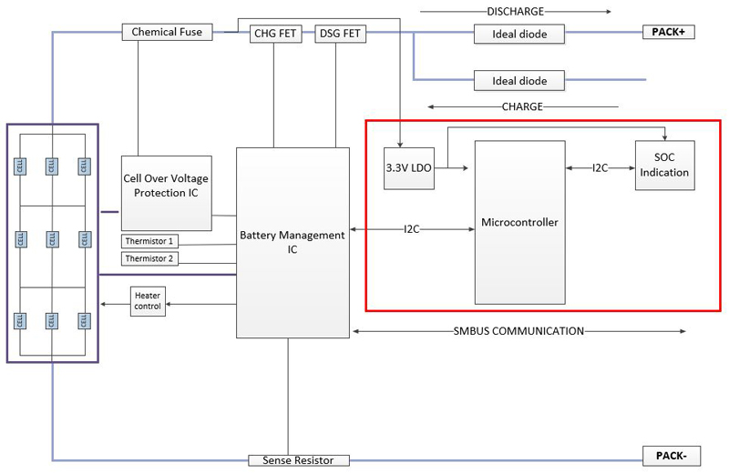
Figure 2: Section in architecture that can be disabled
Design considerations to minimize power consumption
The design considerations listed below extends from defining the architecture of the pack, continuing to hardware and software implementation and final test and verification.
1. Operating modes: It is desirable to have multiple operating modes for the pack that varies in the number of tasks performed and in the period for which they are repeated. The current consumed in these modes are also different. The various operating modes are listed below:
a. Normal mode: This is the mode that the pack is in when connected to an application device or is being charged. In this mode, all the electronic components are in full operating state and consumes the maximum power. All measurements, calculations and data updates happen at the highest frequency.
b. Sleep mode: The pack enters this mode when it is removed from an application’s device for a predetermined amount of time. The measurements, calculations and data updates happen at a less frequent time interval. Some of the electronic components that are not critical are disabled to conserve power. The power consumed in this mode is less than the power consumed in normal mode.
c. Shutdown mode: The pack enters the shutdown mode when there is no external connection or activity for a prolonged period of time. The time duration prior to entering shutdown mode can be in hours or days depending on the application and customer needs. In this mode, almost all electronic components are disabled, and the pack consumes the lowest power. Some battery packs have a switch to allow the user to shut down the pack externally.
In addition to having these modes for the pack, individual components such as a BMS and microcontroller can be programmed to have these modes.
2. Architecture for the pack: Defining the architecture is one of the first stages in the design and the remaining design activities such as schematic, layout and software design follows this. While defining the architecture, it is important to define sections that can be selectively disabled to conserve power in the operating modes defined above. Consider the architecture shown in Figure 2 for a battery pack. The section inside the red box can be disabled in sleep and shutdown mode to conserve power. It includes the microcontroller, user interface display and pull-ups for I2C communication. The microcontroller may be included in the components which are disabled as its role is primarily to support the user interface while in normal mode, so it does not take part in protecting the pack from abnormal conditions.
3. Component selection: Component selection plays an important role in minimizing the power consumption of a battery pack. There are multiple options available for each component, from which the designer must choose the right one for the design. It is desirable to choose the one that consumes the least current, without compromising the functionality. Table 1 compares the current consumption for BMS ICs that support a 4S battery pack and 3.3V LDO ICs. These components are commonly used in a Li-ion battery pack. The difference in current consumed for each of the two options can be clearly noted. The capabilities and features offered by each of them are different. It is up to the designer to understand the trade-offs and make the right choice.
4. Schematic and layout: Since it has been identified that certain sections in the battery pack architecture can be selectively disabled, the designer must add switches to turn off power to these sections whenever required. The control signals for the switches also need to be defined, which can come from the BMS, the microcontroller, or from the application’s device. It is desirable to use high values for pull-up resistors to minimize power lost in the pull-ups. The layout plays an important role when the pack is discharging or charging but is less critical in sleep and shutdown mode. It is always desirable to make sure the traces are wide enough to carry the rated power to minimize heating effects.

Click image to enlarge
Table 1: Current consumption comparison for various ICs
As mentioned above, there are always trade-offs that the designer must consider during various stages of the battery pack design process. For example, an IC with low power consumption may be more expensive than the one with higher power consumption, or the performance of the ICs could be different. In addition to completing the design with an intent to minimize the power consumption, it is important to test and verify the power consumed by the pack. These actual measurements must align with the theoretical calculations. At Inventus Power, we have successfully designed 10.5Ah battery packs that can survive 85 months in storage, starting at only 25% SOC using the design considerations mentioned in this article.