Leveraging multilevel GaN inverter topologies and advanced magnetic components for higher efficiency and power density
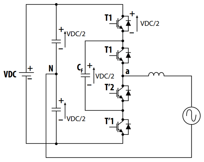
Figure 1: Simplified three-phase flying-capacitor inverter topology
The global transition toward a decentralized renewable energy infrastructure has fundamentally changed the voltage and density requirements of utility-scale Energy Storage Systems (ESS). To reduce conduction losses, minimize cable cross-sections, and optimize structural balance-of-system (BOS) costs, modern ESS designs are rapidly migrating from legacy 400 V and 600 V battery topologies up to 1000 V and 1500 VDC operating thresholds. While higher string voltages offer linear improvements in power delivery efficiency, they simultaneously burden the power electronics conversion stage. Inverters must efficiently process large amounts of power while meeting increasingly stringent requirements for efficiency, thermal performance, electromagnetic interference (EMI), and system size.
Traditional two-level inverter architectures can struggle to balance these competing requirements, particularly as switching frequencies increase and designers seek to leverage the benefits of wide-bandgap semiconductor technologies such as gallium nitride (GaN). To overcome these physical limitations without compromising efficiency, advanced power conversion systems are turning to multilevel topologies. Specifically, the three-level flying capacitor (FC) inverter architecture—when paired with high-speed Wide Bandgap (WBG) Gallium Nitride (GaN) semiconductors—presents a highly effective path forward. By splitting the high-voltage stress across multiple staggered devices, this topology permits the use of lower-voltage, higher-performing 650 V GaN FETs within a 1000 V system environment.
Achieving the true size and efficiency advantages of this architecture, however, requires a complete re-evaluation of the passive magnetic filter components.
The Role of Flying Capacitor Inverters in Modern Energy Storage Systems
Battery energy storage systems rely on bidirectional power conversion to transfer energy between battery packs and the electrical grid. As system power levels increase, converter efficiency becomes a critical design parameter because even small efficiency improvements can significantly reduce thermal management requirements and operating costs.
The foundational benefit of a three-level flying capacitor inverter lies in its ability to generate an intermediate voltage step. This intermediate step effectively cuts the voltage stress precisely in half across every active semiconductor switch. This voltage stress reduction benefit can be clearly realized as each phase leg in a standard three-phase plus neutral configuration incorporates four series-connected power switches and a floating "flying" capacitor that acts as an auxiliary voltage source. The three-level flying capacitor inverter efficiently regulates these power switches to exactly half of the total DC bus voltage (VDC/2).
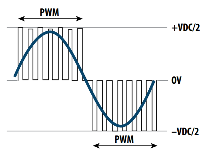
When operating on a 1000 V ESS battery bus, the voltage across each 650 V-rated GaN FET never exceeds 500 V during normal operation. This structural advantage dramatically drops switching losses, which scale quadratically with voltage stress. Furthermore, the interleaved pulse-width modulation (PWM) switching scheme creates an incredibly advantageous phenomenon at the output node: frequency multiplication. By phase-shifting the control signals of the complementary active switches, the effective switching frequency seen by the output filter inductor is doubled relative to the base hardware switching frequency of the transistors. For example, if the individual GaN FETs are driven at a base frequency of 62.5 kHz, the output ripple voltage across the filter phase inductor behaves as if it is being driven at an equivalent 125 kHz. This frequency multiplication provides a dual-fold benefit to the magnetic system design.
As shown in Figure 1, strategically placed capacitors create intermediate voltage steps that allow the inverter to produce a more finely controlled output waveform. First, because the peak-to-peak voltage step is halved (from VDC down to VDC/2) and the frequency is doubled, the physical inductance value required to restrict the peak-to-peak ripple current to a targeted 20% threshold is reduced by a factor of four compared to a standard two-level inverter. Second, smaller required inductance values translate directly into physically smaller inductor footprints, drastically boosting the volumetric power density of the conversion stage. These are illustrated in PWM waveform in Figure 2.
Click image to enlarge
Figure 2: Conventional two-level inverter PWM waveform
One example of this approach is Texas Instruments' TIDA-010957 reference design, a high-power three-phase flying-capacitor inverter platform developed to demonstrate the benefits of GaN-based multilevel power conversion. The design targets applications that demand high efficiency, compact size, and high-performance operation, making it relevant to emerging energy storage and power infrastructure systems.
Addressing the Magnetics Bottleneck at High Frequencies
Although the multilevel architecture drastically reduces the required bulk inductance value, it places extreme thermal and magnetic performance demands on the passive components. Operating at an equivalent switching frequency of 125 kHz introduces severe high-frequency core and copper losses that can easily undermine the gains achieved by GaN semiconductors if the magnetics are poorly optimized. Traditional round-wire, powder-core inductors suffer intensely from parasitic AC proximity and skin effects at these frequencies. As alternating current flows through a round conductor, the internal magnetic fields force current distribution exclusively to the outer skin of the wire. In multi-layer windings, the proximity effect further crowds current into localized areas of the conductor, driving up the effective AC resistance (RAC) and creating localized thermal hotspots.
To eliminate these high-frequency penalties within the Texas Instruments TIDA-010957 high-power three-phase flying capacitor inverter reference design, specialized magnetic structures were custom engineered. Designed specifically to handle the high-power density requirements of storage-ready 1000V inverter platforms, these components have now moved into full engineering sample production to meet broad market demand.
Advanced Primary Phase Filter Inductor
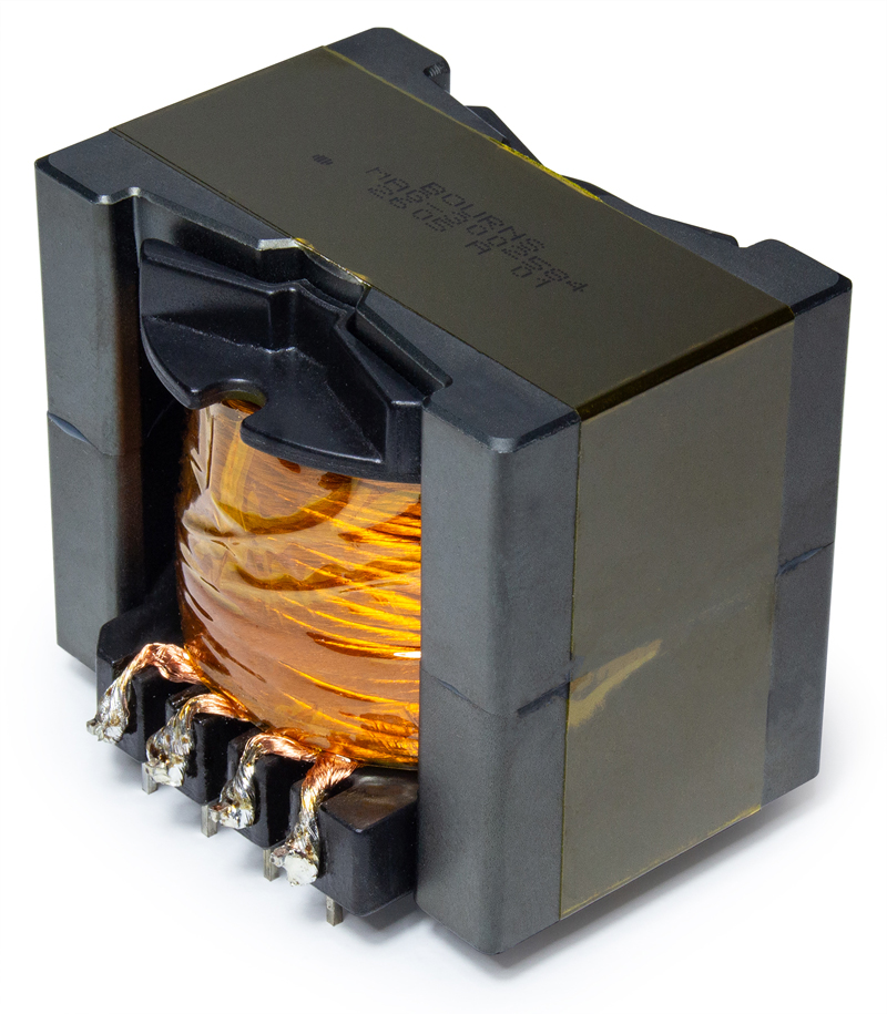
To serve as the primary phase filter inductors in the TIDA-010957 bidirectional power stage, Figure 3 shows the Bourns Model MAG-3002584 high-power inductor developed for the design. This component provides a specialized 87 µH inductance optimized to handle the 125 kHz equivalent ripple current frequency while preserving an ultra-low profile. The core design choice driving its peak efficiency (>98.5%) is its flat-wire winding construction. Unlike standard round wire, flat helical windings expose a significantly larger surface area relative to the conductor's cross-sectional area. This expanded surface area vastly lowers skin effect losses.
Click image to enlarge
Figure 3: Bourns® Model MAG-3002584 high-power inductor
Additionally, flat-wire technology enables a near-perfect volumetric window utilization factor within the magnetic core, minimizing the mean turn length and driving down the Direct Current Resistance (DCR) to an absolute maximum of just 10.1 mΩ. Lower DCR directly curtails I2R conduction losses when the ESS is delivering heavy currents to the grid. Magnetic saturation behaviour is another critical criterion for ESS applications, where sudden grid load steps can induce momentary current spikes. The MAG-3002584 features a robust 42 A saturation current (Isat), maintaining stable inductance linearity across a broad operating temperature envelope (-40 °C to +125 °C) to ensure the control loop never destabilizes under heavy loads.
Importance of Mitigating High-Voltage EMI
Transitioning a three-phase system up to a 1000V battery DC link introduces intense high-frequency common-mode (CM) and differential-mode (DM) electromagnetic noise due to the high dv/dt edges inherent to GaN switching. Without effective noise suppression at the input/output boundaries, these high-frequency currents circulate through system ground loops, threatening grid compliance and degrading adjacent Battery Management System (BMS) signal integrity.
Click image to enlarge
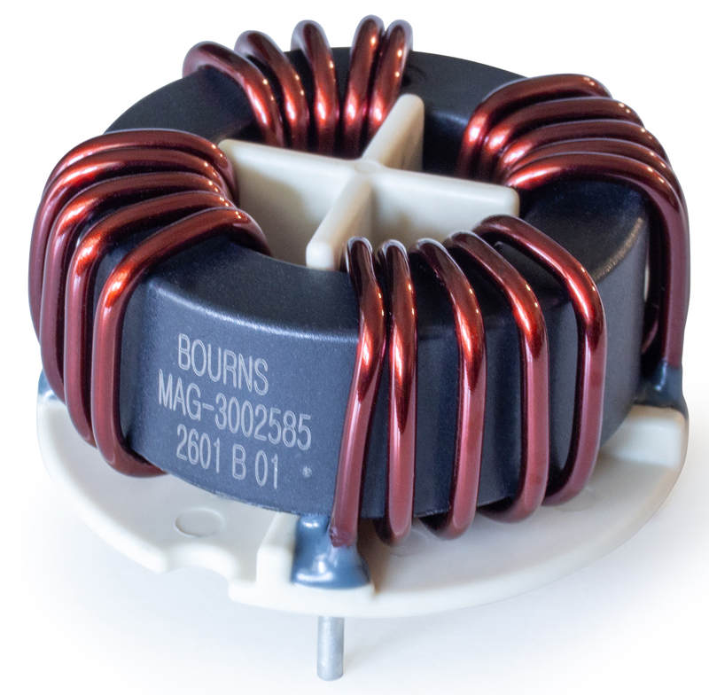
Figure 4: Bourns® Model MAG-3002585 4-phase line choke
To attenuate this noise without adding massive bulky filtering arrays, a 4-phase line choke was needed for the TIDA-010957 architecture. Serving as a multi-line common-mode filter, this component presented in Figure 4 features a unique four-winding configuration that integrates all three phases plus the system neutral onto a single unified magnetic structure. The core material selection represents a major technological leap beyond traditional manganese-zinc (MnZn) ferrites. The advanced line choke design utilizes a nanocrystalline core structure, which delivers exceptionally high magnetic permeability across a wide frequency spectrum. This elevated permeability allows the choke to achieve substantial common-mode impedance with far fewer wire turns. Fewer turns translate directly to an extremely low typical DCR of only 1.5 mΩ per winding.
Consequently, the line choke effectively suppresses high-frequency differential and common-mode noise while generating virtually negligible insertion losses and heat. This unified component replaces multiple discrete filters, drastically saving printed circuit board (PCB) real estate and helping the system achieve a higher overall power density.
The Bigger Picture: Cohesive BMS and Power Stage Integration
While optimizing the main bidirectional DC/AC inverter stage is paramount for handling high-voltage battery lines, achieving absolute system reliability requires a holistic engineering focus across the entire ESS framework. High-voltage 1000 V battery banks are managed by complex, multi-layered Battery Management Systems that rely on ultra-isolated signal and power channels to monitor cell voltages and pack state-of-charge safely. Flying-capacitor inverter architectures, particularly when combined with GaN switching devices, offer a compelling path toward achieving these objectives by reducing switching losses, improving waveform quality, and enabling higher power density.
However, semiconductor performance alone does not determine converter efficiency. Optimized magnetic components remain essential for energy storage, filtering, EMI suppression, and thermal management throughout the power conversion chain. By combining three-level flying capacitor architectures with customized high-efficiency power inductors like the MAG-3002584 and ultra-permeable chokes like the MAG-3002585, system designers can comfortably bridge the gap between high-power density and operational longevity. These magnetic components prove that targeted material engineering can eliminate the passive filter bottlenecks of modern wide-bandgap designs, clearing the way for highly efficient 1000 V grid-tied energy storage solutions.