As well as supplying power, supplies also provide a barrier between a lethal voltage and anything that you can touch
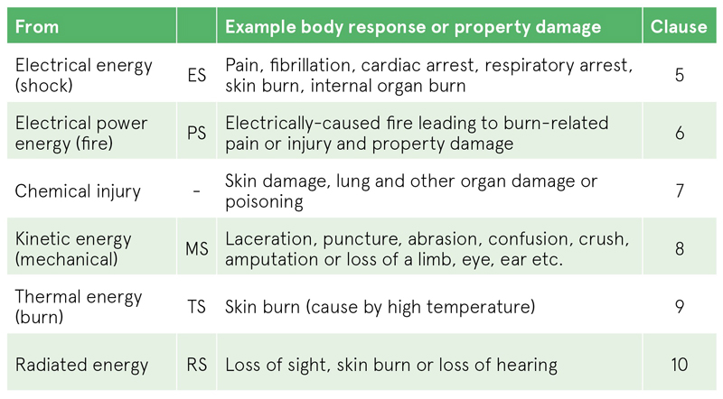
Table 1: Potential hazards from a power supply
No power supply should produce other hazards itself, which include fire, fumes, releasing dangerous chemicals, emitting harmful radiation and causing physical injury from sharp edges and falling/flying objects or burns from hot surfaces. In a power supply design, all these effects must be considered and evaluated by accredited test facilities against international standards before the product can be placed on the market. European CE marking, for example, is conditional on all relevant ‘directives’ being met, with the onus on the manufacturer to identify which to apply. Table 1 is taken from EN 62368-1, the safety standard now common for power supplies, elaborating on the various hazards and their effects.
A product must be safe for users, operators and maintenance personnel, but safety engineering has a much wider scope, including ‘protection’ for the environment and for other products in the locality. RoHS, the Restriction of Hazard Substances legislation is a good example, where currently ten substances must be restricted in their use (not necessarily banned) because they are identified as hazardous to the environment and health. RoHS is a ‘vertical’ product-specific EU directive. This goes in hand with WEEE, the Waste from Electrical and Electronic Equipment directive which controls how products are treated at the end of their life. REACH: Registration, Evaluation, Authorisation and Restriction of Chemicals has a parallel effect, requiring manufacturers to control the chemicals used in their products. REACH is a ‘horizontal’ EU regulation controlling the risks associated with chemical substances used in a manufacturing process, throughout their whole life cycle.
On a wider stage, the environment is safeguarded by limits to no-load and standby losses from power supplies along with efficiency targets under load. The EU ‘Ecodesign Directive’ for energy-related products sets limits, as does the US department of Energy (DoE) with its stringent Level VI requirements. Particular product areas have their own voluntary targets such as the 80+ certification program for server power supplies.
Electromagnetic Compatibility (EMC) is an important issue in power conversion equipment. Standards have to be met for conducted and radiated emissions to avoid unwanted effects on other equipment and conversely, power supplies must be immune to interference. The EU EMC directive applies. While these are safety issues only in terms of effects on equipment, EMC filters do have electrical safety considerations – specifically earth leakage current, so when designing for product safety, a holistic approach must be taken.
The standards and their governance
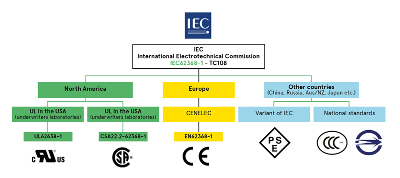
Potentially hundreds of safety, EMC and material standards apply to a power supply design and they can vary with the end application and geographical market. While some countries have established their own regulations, these mostly originate from the International Electrotechnical Commission (IEC) and are adapted and adopted locally. In Europe for example, the IEC standards are ‘harmonised’ as EN (Euronorm) documents which become law. Typically, the numeric designation stays, so for example, IEC 62368-1 becomes EN 62368-1. Even within the EU, members states can have their own deviations from the EN standards, so the IEC operates a ‘CB scheme’, which allows a test report by an accredited laboratory to be accepted by any member state with a minimum of extra testing and verification. Figure 1 shows the hierarchy of the major standards organisations and the applied certification marks for IEC 62368-1.
Click image to enlarge
Figure 1: The major standards organisations for electrical equipment
Safety terminology
Electrical equipment falls into three major classes. Class I has a protective earth connection (PE), which guarantees that in the event of a failure making accessible conductive parts live, dangerous current will flow to earth rather than to a user, blowing a fuse. Class II equipment has no PE but the protection is provided by an insulating barrier to any dangerous voltage of minimum thickness and robustness so there is no accessible conductive part. Class III equipment is supplied by a separated extra-low voltage which is considered inherently safe from electric shock. There is actually a Class 0 which is identified as a product with accessible conductive parts and with no PE, but this is generally disallowed as being inherently unsafe.
Terminology used by the major standards can sometimes be confusing, the list below is some common terms seen:
· Primary: A circuit directly connected to the incoming AC Mains Supply
· Secondary: A circuit with NO direct connection to the primary (e.g. isolated via a transformer or fed from a battery supply)
· Hazardous Voltage (HV): A Voltage exceeding 42.5 Vac pk or 60 Vdc (e.g. AC Mains Supply)
· Low Voltage (LV): A Voltage NOT exceeding 42.5 Vac pk or 60 Vdc
· Extra Low Voltage (ELV): A Voltage that is LV and is separated from the HV via some sort of insulation (protection)
· Safety Extra Low Voltage (SELV): A secondary circuit who’s voltage is ELV even under HV fault condition (e.g. L or N or E open)
· Hazardous Energy Level: Stored energy of 20 J or more, or greater than 240 VA at 2 Vac or more
· Protective Earth (PE): A secure connection to ground
Protection against electric shock is achieved by insulation or physical separation. For insulation, the guiding rule is that two measures of protection must always be present to give sufficient confidence of safety. One measure on its own is called basic protection, so to achieve two measures, an independent supplementary level must be added. An example in an AC-DC power supply is the combination of a minimum distance from a dangerous voltage to accessible metalwork for a BASIC level, combined with secure earthing of the metalwork as supplementary protection, so a fuse blows if the basic insulation fails. Together the two measures of protection are called DOUBLE insulation. A single layer of insulation or wide separation that is as unlikely to fail as double insulation is also called reinforced insulation. Users will also see the terms operational or functional isolation - these relate to insulation or spacing that enables a circuit to work correctly but does not provide any guaranteed safety barrier.
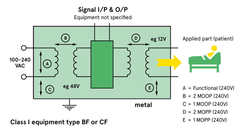
In medical products, the terms are different; Measures of Protection (MOPs) are referenced, with one MOP equivalent to basic isolation and two MOPs equivalent to double or reinforced. MOPs are separated into Measures Of Operator and Patient Protection (MOOPs and MOPPs) with different requirements on the separation distances. Figure 2 is an example of the most stringent use case in medical, with the measures of protection required. This is for patient protection, cardiac floating (CF) with unspecified signal connections, Class I equipment.
Click image to enlarge
Figure 2: An example of medical measures of protection required
When selecting a power supply, it is important to note that measures of protection are only achieved under specified conditions. For example, a maximum system voltage, a maximum altitude of operation, a specified environmental pollution degree and system over-voltage category. If the product operates outside of these limits, its safety certification is invalid.
Testing to ensure safety
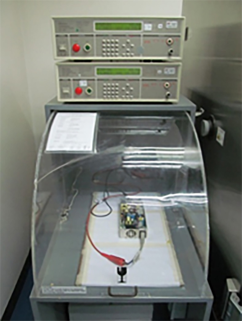
Power supplies undergo ‘type testing’ at certified laboratories to qualify for safety certification. These tests are on samples representative of the final design and production process, so are a ‘snapshot’ in time but are backed up by regular factory inspections by the safety agencies concerned. Parts are also 100% tested for safety at various points in the production process. Typically, isolation transformers are tested individually and then the finished product is tested for dielectric strength (Figure 3) and earth bonding. Again, these are one-time tests to give an indication of the likely safety of the product over its lifetime. Users should perform periodic safety testing in the application but with reduced stress levels, as continual unnecessary testing can actually degrade insulation systems.
Click image to enlarge
Figure 3: A typical automated production dielectric strength test arrangement, courtesy Advanced Energy