Power Design Challenges in 1500 VDC Photovoltaic Systems
Raising energy efficiency is essential to ensure the financial viability of photovoltaic power generation
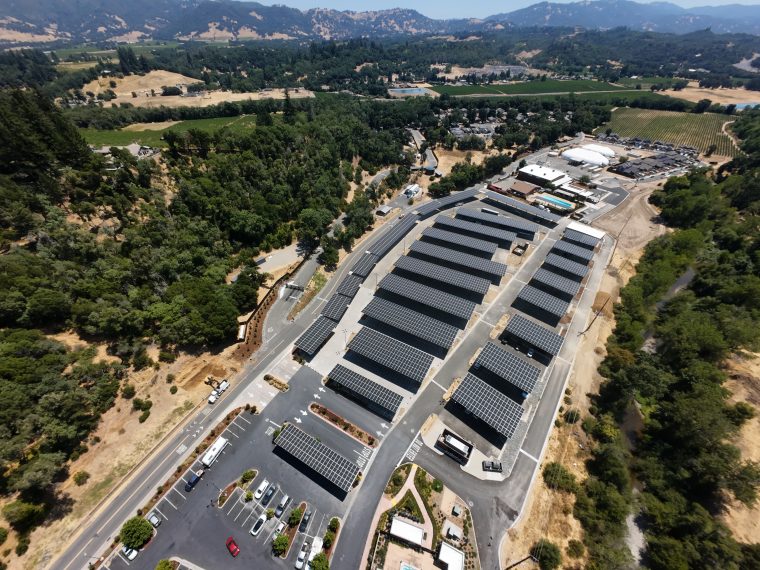
Figure 1. Key functions of a multi-MW grid-tied PV generator
Although government subsidies for photovoltaic (PV) power generation tend to come and go, installed capacity continues to increase. From a base of 178 GW in 2014, global capacity is predicted to hit 540 GW in 2019.Europe has the largest share, projected to reach 158 GW in 2019, although growth is faster in other countries such as China and the United States, where installed capacity is expected to increase four-fold and three-fold respectively in the same period. A successful solar industry is also good from an economic point of view, directly employing around 55 million people in 2014.
If PV power generation is to live up to these predictions, and grow further, the cost in terms of $ per Watt must continue to reduce. One barrier is the generally low efficiency of the panels themselves. Today’s most efficient monocrystalline cells operate at around 25% efficiency, and this is already close to the theoretical maximum for the technology.
Raising Operating Voltage to Save Energy
Clearly every joule harvested from the sun’s rays is precious. Frugal energy management is essential to minimize losses in each part of the system, from the dc output of the solar modules to the ac feed to the grid (Figure 1). Connecting multiple modules in series to produce a high-voltage dc output helps by reducing the current and hence lowering I2R losses between the photovoltaic arrays and the inverter. It is quite common for grid-connected systems to operate at 1000 Vdc. A typical system comprises 22 modules connected in series to create a string, with each module containing 90 cells to produce an output voltage of about 45 V. Such a string could generate peak power of 5.5 kW, allowing a 15 MW installation, for example, to be configured by combining 2727 strings.
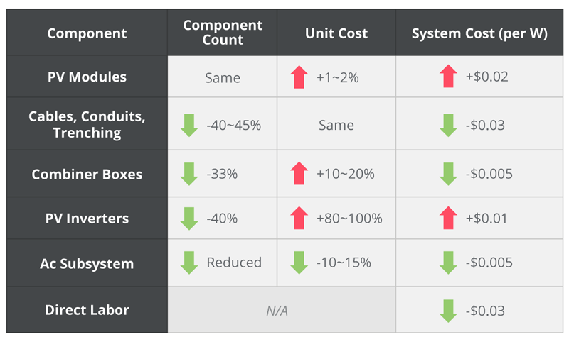
By increasing the number of modules per string to raise the output voltage to 1500 Vdc, the maximum current entering each combiner could be further reduced to 66.6% of the value at 1000 Vdc. Resistive cable losses would be even lower, at just 44.4% of the previous value. This gives system designers greater flexibility to raise energy efficiency as well as lower installation costs by reducing cable sizes and specifying smaller connectors. In addition, fewer strings are needed to achieve a given output power, thereby reducing the number of required combiner boxes. Assuming each box handles 20 strings, a 15 MW installation would require only 94 boxes compared with 137 at 1000 Vdc: a 31% reduction. GTM research has calculated that designing a 10 MW plant to operate at 1500 Vdc reduces deployment costs by about $400K compared with a 1000 Vdc system (Figure 2).
Click image to enlarge
Figure 2. Potential deployment saving at 10 MW by moving from 1000 V to 1500 V
Design Challenges at 1500 V
These potential cost savings and efficiency gains are certainly attractive, but insulation must be uprated throughout the system, and the combiner boxes and inverter must also be capable of operating at the higher voltage. Thankfully suitable inverters are already in the market, and some of these products are based on the latest wide-bandgap semiconductors, which deliver greater efficiency than silicon-based alternatives.
However, another important aspect in the design of 1500 Vdc systems is the fact that these PV combiners and inverters need to derive their own low-voltage source from the 1500 Vdc line, to power monitoring and control circuitry. Small dc-dc converters that can provide this are not readily available with an input-voltage range wide enough to operate at 1500 Vdc while also being able to handle dips in the string output voltage reaching as low as 200 Vdc. This calls for an input range of at least 7.5:1, which is not a common specification.
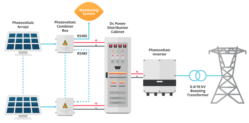
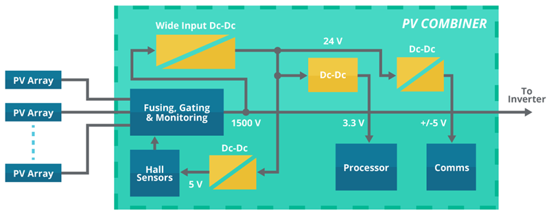
Figure 3 illustrates the power architecture of a solar combiner unit containing a wide-input dc-dc converter with a 24 Vdc output, which is used to supply communications and processing/sensing modules via additional isolated and non-isolated converters. Fully reinforced safety isolation is needed for the main high voltage dc-dc converter, typically specified as 4000 Vac.
Click image to enlarge
Figure 3. Internal power architecture of solar combiner box
Safety Considerations
As far as safety is concerned, the applicable standard is IEC 62109-1 ‘Safety of Power Converters for use in Photovoltaic Power Systems’, which is relevant to systems up to 1500 Vdc. Part 1 of the standard specifies general requirements, and part 2 defines specific requirements for inverters. The scope of IEC 62109-1 encompasses design and construction methods to ensure protection against electrical shock, mechanical hazards, high temperatures, fire, chemical hazards, and other potential dangers.
The standard also includes a reference to IEC 60664 ‘Insulation Coordination for Equipment within Low-Voltage Systems’. Of particular relevance to dc-dc converters is the requirement for testing to verify the absence of partial discharge, which can occur when microvoids in the insulation break down at high voltages leading to degradation and eventually complete failure. Testing is very relevant to 1500 Vdc operating voltages and requires special construction of the dc-dc converter isolation barrier.
The insulation requirements of IEC 62109-1 depend on the system voltage, installation over-voltage (OV) category and pollution degree (PD) of the environment. OV category II is used for the PV panel circuits in systems with a 1500 Vdc bus, with minimum impulse withstand of 6000 V. For the grid-connected inverter stage, OV III is used and the impulse-withstand requirement is 8000 V.
As an industrial-grade application with some environmental protection, the equipment is subject to PD 2. This allows only non-conductive pollution with occasional condensation. IEC 62109-1 contains many further specifications that must be considered.
In addition, the UL 1741 standard is applicable in the US. This covers the more general application of ‘Distributed Energy Resources’ and includes requirements for ‘converters and microcontrollers.
New Auxiliary Power Topology
These standards impose specific performance requirements on auxiliary dc-dc converters working in this environment. The very wide input range and high maximum input voltage are extremely challenging for standard flyback or forward converter topologies. A more complex topology is needed to limit stresses on components in the presence of extremely high internal peak voltages and currents that can arise as pulse width is varied to regulate the output.
Protection is also extremely important, to ensure the converters can continue operating despite frequent ‘brown-outs’, as the input dips below the minimum value when illumination levels are low or if the panels become shaded. These and other fault conditions that can occur in a remote installation, such as overloads, short circuits or over-voltages, must be prevented from damaging the converter. The converters must also be able to withstand high operating temperatures, as PV systems are preferably located in full sun to maximize energy harvesting potential. It is also important to meet agency-specified isolation ratings.
Considering the combined effects of all these individual challenges, designing a 1500 Vdc wide-input dc-dc converter for PV applications is not a trivial task.
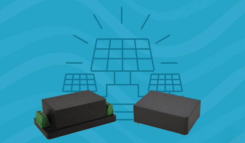
CUIhas recently launched the AE seriesof dc-dc converters for PV applications operating at 1500 Vdc (Figure 4). These are designed to handle the 200 to 1500 Vdc input range needed for use in solar auxiliary power supplies and are available in 5, 10, 15 or 40 W power ratings. Output voltage options are 5, 9, 12, 15 or 24 Vdc. The converters are approved to EN 62109-1, the European version of IEC 62109-1, with 4000 Vac isolation and rated operation up to 5000 meters altitude. Some models also meet UL 1741. A choice of encapsulated board mount, chassis mount or DIN rail formats is available, and the converters can operate at up to 70°C with no derating.
Click image to enlarge
Figure 4. CUI’s AE series of dc-dc converters operate with input voltage from 200 to 1500 Vdc
Drop-in Auxiliary Power for 1500 Vdc PV systems
Maximizing energy-conversion efficiency is the most important objective when designing industrial PV generating systems for installations up to the GW level. Raising the solar-array output voltage to 1500 Vdc supports this goal, although comprehensive control and monitoring are needed to achieve the best performance. The auxiliary power supplies used to sustain these functions must comply with reliability and safety standards, while at the same time being able to operate from an input voltage that can vary widely from as little as 200 Vdc up to 1500 Vdc. The latest generation of dc-dc converters from CUIconceived to satisfy these challenges presents a drop-in solution for PV system designers and integrators.
CUI Inc.