Synchronous rectification of an LLC output
With demand for high efficiency becoming part of product specification across the whole load range, design engineers are reviewing AC-DC power supply topologies with the specific aim of reducing power loss. One such topology offering class-leading efficiency is illustrated in Figure 1. This article examines claims by IC manufacturers to have dealt with the last remaining large source of power losses in this topology: the output rectification stage. Previous enhancements to this topology have produced improved Power Factor Correction (PFC) control ICs for the interleaved Boundary Conduction Mode (BCM) stage, and new LLC control ICs which enable more efficient designs. So now losses in the output rectification stage of the LLC resonant converter tend to dominate the power losses budget. To make the next step forward in efficiency, synchronous rectification is required. Two newly introduced ICs, from International Rectifier and Diodes Inc, are now being promoted as potential solutions to the problem. Before these devices reached the market, synchronous rectification for LLC resonant converters could not practically be implemented because of the complexity and difficulty of the technique.
The reality of synchronous rectification in resonant LLC circuits For voltage-fed circuits, typical of the Pulse Width Modulation (PWM) or series-parallel resonant topologies, additional windings or tapping from the power transformer would suffice for driving the synchronous rectification circuits. The LLC resonant topology is different: since it is a current-fed, capacitor-loaded structure, it cannot use the power transformer waveforms to drive synchronous rectification circuits. This is because the voltage on the secondary windings is connected to the output via the mosfet during its conduction time, and therefore holds the winding voltage until the mosfet switches off. One method of resolving the problem is to sense the current flow and voltage around the mosfet. This requires the following functions:
- Current sensing (of Ids)
- Voltage sensing (of Vds)
- High-speed logic
- High-current gate drive
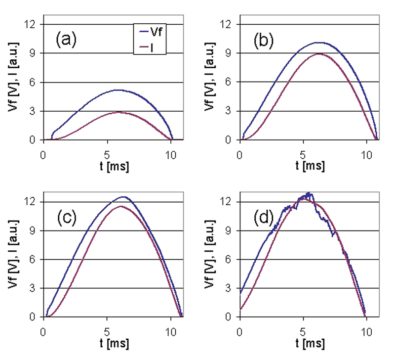
It is interesting to see in both diagrams the fast gate drive voltage. In ~200ns after detection of the parasitic diode forward volt drop within the MOSFET, Q1 turns on, reducing its voltage (Ch1 - Vds). In both tests, Q1 Vds is higher than expected. This may be due to the circuit inductance and to the capabilities of the oscilloscope. At full load, the gate drive voltage reduces as the sinusoidal current starts reducing. This is probably due to the inductance of the circuit and the inductance of the Q1 TO220 package. Improved layout and selection of a lower inductance packaging should resolve the issue. As before, Figure 4 details the waveforms at F.L. and Figure 5 details the waveforms at 25% of F.L. for the test circuit using the IR1168 device.
Like the ZXGD3103, the IR1168 test circuits reveal a fast gate drive voltage - in <200ns after detection of the parasitic diode forward voltage drop within the mosfet, Q1 turns on, reducing its voltage (Ch1 - Vds). As before, Q1 Vds is higher than expected, probably for the same reasons. In the full-load test circuit, the early termination of the gate drive voltage (Vgs) as the sinusoidal current starts reducing is probably due to the inductance of the circuit and the inductance of the Q1 TO220 package. As in the previous test circuit using the ZXGD3103, improved layout, reduction of resistances and selection of a lower inductance packaging should resolve the issue. So how much power does implementation of synchronous rectification save? The key reason for implementing synchronous rectification is to save power. The tables below detail the key parameters of interest.

With improved layout and mosfet package selection, both synchronous rectification circuits could exhibit even higher efficiency; the small differences in efficiency between the ZXGD3103 and IR1168 circuits shown in the tables are therefore not material. What is clear is that substantial power savings are possible by implementing circuits that can be designed with little trouble by following the manufacturers' application guidelines. What is also clear is that the threshold at which a power saving can be observed appears to be at around 25% of F.L. and above. At full load the Schottky diodes warm up the heat sink to the extent that a small fan is required for continuous operation. By contrast, the mosfet in the synchronous rectifier circuits can be operated at full load without a heat sink, and indeed in both cases was cool to the touch. This points to the possibility of a bill-of-materials savings to be made from the elimination of heat sinks and fans. In conclusion, with the introduction of the ZXGD3103 and IR1168, the implementation of synchronous rectification of the output stage of LLC circuits has become a practical possibility. This new technique appears to deliver power savings anywhere from 25% of full load up to 100% of full load. For more information on implementing high-efficiency power supplies, contact any branch of Future Electronics. The ZXGD3103 and IR1168 parts mentioned in this article are available to buy from Future Electronics. www.futureelectronics.com


