Power inductors and peak-current handling capability
Understanding magnetic-core saturation characteristics can improve power circuits' robustness and performance
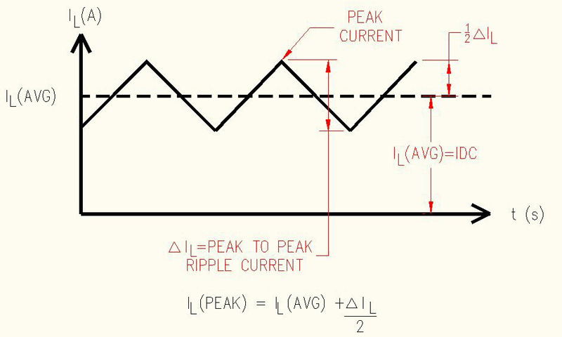
Figure 1: Inductor-current waveform
As high-tech electronic products and their power supplies continue to shrink in size, design engineers should look closely at the peak-current handling capability of power inductors. Design engineers are called upon on a daily basis to reduce the size of electronic products. This ultimately means that they will make an attempt to reduce the size of the power supplies' inductors and transformers. Design engineers have been able to reduce the size of inductors and transformers by increasing the magnetic components' operating frequencies. However, there are times the increase in frequency is limited. Understanding the peak-current handling capability of inductors can help identify opportunities to reduce the size of an inductor further. Peak current defined When selecting inductors, engineers have to ensure the component can handle the maximum peak current their circuit generates (figure 1). Therefore, inductors are rated to handle what is more commonly known in magnetics as saturation current, ISAT. Saturation current is the DC current that causes the inductance without current to drop, typically 10 to 20% as a result of core saturation. In addition, saturation is the point when an inductor can no longer store energy and instead shows a drop in energy storage and inductance. From the inductor current waveform, in figure 1, it is evident that the inductor peak current is the sum of the average inductor current and half of the peak-to-peak ripple current. It is worth mentioning that the peak-to-peak ripple current illustrated in figure 1 is what causes core losses in inductors. This is an area of occasional confusion in power supply design.
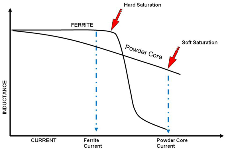
Hard saturation versus soft saturation When taking a closer look at how different materials used in power inductors saturate it becomes clear that some materials will saturate hard and other materials will saturate softly. Hard saturation is simply when the inductance abruptly drops once the current reaches ISAT. Some would say hard saturation is like something falling off a cliff. Soft saturation is simply a gradual drop in inductance (figure 2). As is shown in figure 2, hard saturation is a characteristic of ferrite materials, which are common in power inductors. Soft saturation is seen in power inductors that utilize powder cores, also known as distributed gap materials. Powder cores are more common in custom applications that require soft saturation and the ability to handle higher saturation currents. With ferrite cores and the hard saturation mentioned earlier, design engineers may need to choose an inductor with a higher ISAT rating than what they actually need. In other words, they will de-rate the inductor they choose to avoid the abrupt drop in inductance and the circuit stability issues the abrupt drop in inductance may cause. For example, if an engineer has a need for a 10 ?H inductor with an ISAT of 1.4 A, they can choose an RL-9580-1-1.2-100M, which features a saturation current of exactly 1.4 A and a component height of 1.2 mm. However, if the inductor was made with ferrite material, the inductance would drop abruptly once the peak current reached 1.4 A. In many cases the engineer would simply choose a larger component and de-rate it, such as an RL-9580-1-2.0-100M with an ISAT of 2.3 A and a component height of 2 mm. If the engineer carefully tested the first part number mentioned above he may find that this part, with an ISAT of 1.4 A, would work well in his circuit. More importantly RL-9580-1-1.2-100M would be shorter than RL-9580-1-2.0-100M. If the height of the inductor is not critical then RL-9580-1-2.0-100M would be the best choice since its typical DCR of 215 m? is only slightly more than half of the RL-9580-1-1.2-100M's 410-m? typical DCR, and would, therefore, dissipate less power and run cooler. The RL-9580 high current inductor family is manufactured with a composite material that exhibits soft-saturation characteristics.
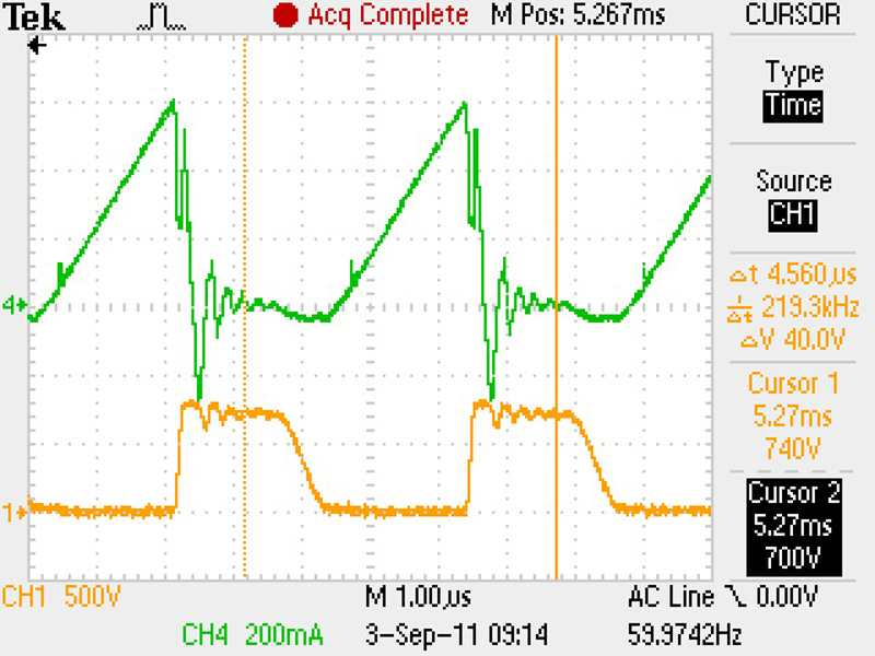
Signs of saturation in the current waveform For those engineers new to power supply design it may not be clear when they are seeing the effects of inductor or transformer saturation in their power supply. A simple oscilloscope measurement of the peak current going through the inductor or primary winding of a flyback transformer (also known as a coupled inductor) will quickly show if the inductor or flyback transformer is saturated. The top waveform in figure 3 is a good example of an inductor that is not exhibiting saturation beyond a 15% drop in inductance. The upward slope is clean and straight. The top waveform in figure 4 is of an inductor clearly exhibiting saturation beyond a 40% drop in inductance. The slope of the waveform is low and the peak is a very narrow spike. If the waveform of the peak current going through the inductor or flyback transformer resembles figure 4 then the inductance value of the inductor or flyback transformer in question and the peak current should be re-confirmed. Once the inductance and peak current value is re-confirmed, a standard inductor with a higher ISAT current should be selected or the number of turns of the custom inductor or flyback transformer needs to be adjusted to handle a higher peak current.
Further confirmation that an inductor or flyback transformer is saturated occurs when the expected full power is not delivered to the load. In order to confirm that the correct inductance and peak current is specified, calculate the power from those values:
where P is the power in watts, L is the inductance in henries, IPEAK is the peak current in amperes, and f is the frequency in hertz. Inductor-design basics Designing a ferrite-based inductor that will saturate by less than 10% is a fairly straightforward process. Once you determine the inductor's size constraints, you can choose an inductor core and calculate the number of turns necessary to support the required inductance and peak current with a 10% or less drop in inductance:
Where N is the number of turns, L is the unductance in henries, IPEAK is the peak current in amperes, BPEAK is the peak flux density in gauss, and Ae is the core area in cm2. The key is to use a peak flux density of 3,000 gauss or less to keep the core losses to a minimum and to keep the drop in inductance to less than 10%. Designing a powder-core based inductor is slightly different, but the inductance and peak current appear in the design formulas in the same way. An in depth analysis of designing with powder cores can be found at www.mag-inc.com and www.micrometals.com. Renco Electronics