Automobile leading-edge technologies allow us to do other “tasks” in addition to actually driving, and a large percentage of these evolve around the handset.
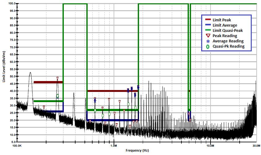
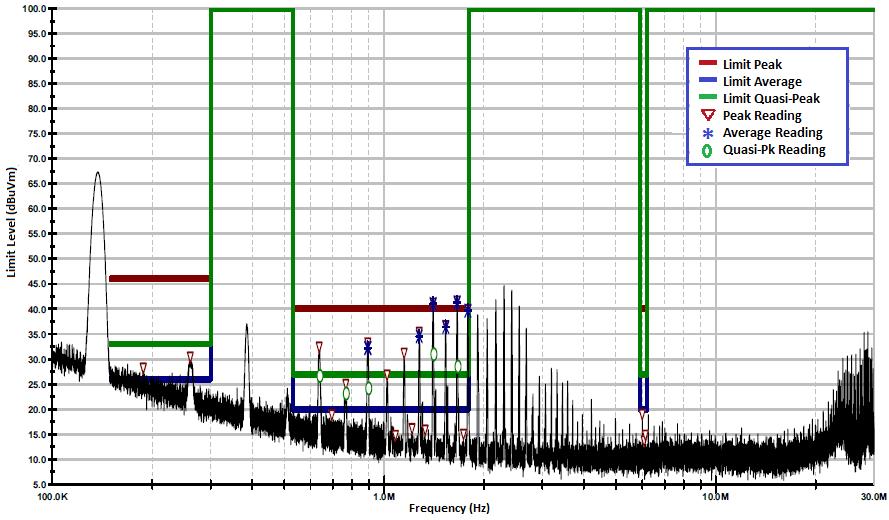
Figure 1 – CISPR 25 Class 5 Initial Testing 100 KHz to 30 MHz
Recently, the Wireless Power Consortium (WPC or "Qi") technology won the technology battle and is now the low power standard for handsets. This fact was further cemented with implementation of the Qi technology by all leading worldwide handset makers.
Car models, with wireless charging available, is now at 100+ models which equates to over 12 million (2.4M OEM, 9.7M after market) vehicles having Qi based systems installed in 2018 alone. The majority are Qi Baseline Power Profile (BPP) or 5W systems. The new direction is for faster charging and higher power, via compliance with the Qi Extended Power Profile (EPP) or 15W capability. This faster charging convenience comes with additional technical hurdles that must be overcome. The three main issues being EMI compliance, efficiency and thermal limitations.
The 15W System
Within the WPC standard, there are sub-categories (e.g. MP-A9) that specify various aspects of the system and configuration of the transmit (Tx) coil that is used. Done for interoperability purposes, the standard defines: input DC voltage, Tx coil size and shape, frequency control (e.g. fixed), power level, and power control (voltage/frequency/phase/duty cycle). The 15W Tx input voltage is 12V, with coil voltages up to 100V due to the resonance mode of operation, and thus has both elevated magnetic (H) and electrical (E) fields meaning potentially stronger radiated noise than Qi BPP 5W systems.
EMI Issues and Solutions
On newer vehicles, numerous RF systems need to co-exist and ensure that they do not affect anything else such as: AM/FM radio, GPS, Bluetooth, WiFi, telematics, etc. A few of these RF systems operate within the 87-205 KHz (up to 300 KHz) frequency range of the Qi EPP system and/or low harmonics. AM radio, 525 KHz to 1705 KHz (in the Americas), is required to be EMI free as it is used as part of the Emergency Broadcast System. New remote keyless entry systems (RKE) operate at 125 KHz as do some tire pressure monitoring systems (TPMS) for driving the initiator L-C (inductance-capacitance) coil circuit.
Automotive applications have very stringent EMI requirements. CISPR 25 (Comité International Spécial des Perturbations Radioélectriques) is a non-regulatory engineering automotive standard that sets conducted and radiated emission limits that must be met for the protection of other on-board receivers and defines these limits over a frequency range of 150 KHz to 2500 MHz.
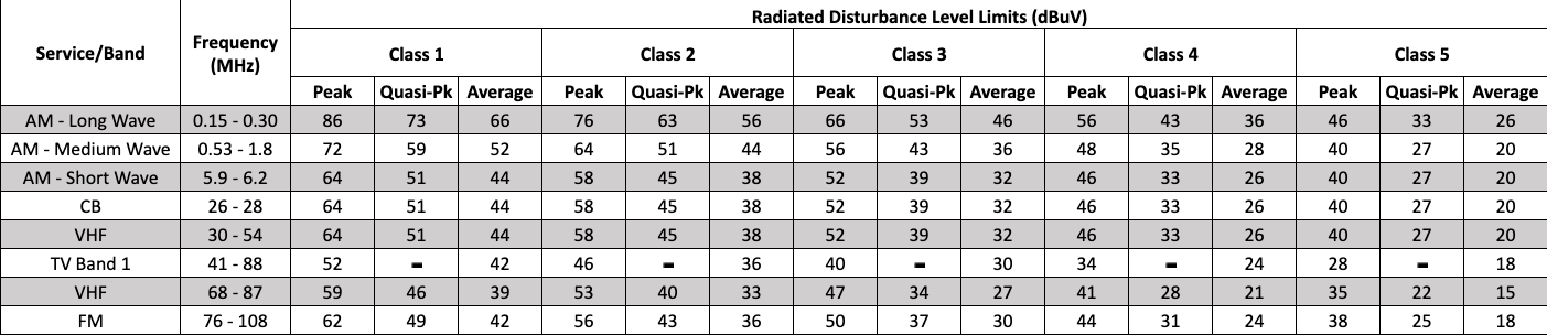
Within CISPR 25, there are classes defining permitted conducted and radiated noise emissions limits, with radiated being the real concern. The radiated Class limits versus bands are given in Table 1 for Peak, Quasi-peak and Average measured voltage up through the FM radio band.
Click image to enlarge
Table 1 - CISPR 25 Radiated Limits by Class
With the increased Qi EPP power levels, meeting Class 4 has been a challenge and to date, no Class 5 system is available in the market. Actual CISPR 25 Class 5 measurement data is provided in Figure 1.
From the plot, this design does not fully pass Class 5 certification but does meet Class 4 requirements. The following sections address some key EMI noise mitigation areas used in the system design.
The first approach of mitigating EMI noise is implementing a fixed frequency system. The Qi standard allows for variable frequency to better "tune" the two sides to improve performance. A changing frequency would make complying with the CISPR 25 stringent EMI noise limits even more problematic. For current Qi EPP designs, the fixed frequency is around 127 KHz.
The next technique is to remove the Tx coil square wave currents and have them be sinusoidal. This approach reduces the noise "spikes" that could be otherwise generated. Using an inductor in the drive circuitry smooths out the square wave current created by the turning ON/OFF of the switches (MOSFETs) and helps to ensure that the switching scheme is "clean" and noise free.
Further EMI suppression can be realized with the addition of a common mode filter (CMF) placed in series with the Tx coil windings. Current through the Tx coil is pure alternating current (AC), which can be considered as 100% ripple current, and has no direct current (DC) content like many power supplies which involve DC current and some allowable ripple current. Therefore, selection of the ferrite material used for this CMF is important and AC core losses must be minimized at the 127 KHz fixed frequency.
Another EMI noise suppression technique is to add EMI suppression magnetic sheets to absorb harmonics and spurious unwanted noise that may emit out of the backside of the main Tx shield. The magnetic sheets remove EMI noise via two methods. First, higher permeability (µ') of these materials yields better shielding (containment) performance of the magnetic flux (φ) and reduces it from being radiated. Next, higher resistive properties (µ") yield better noise suppression through higher core losses for the unwanted frequencies' flux fields remove the EMI noise in the form of heat. This relationship is given in Equation 1.
µ = µ' - jµ" Eq. 1
But having too high of a µ' value can decrease performance. Due to a phenomenon called magnetic coupling (K), having an additional magnetic sheet can shift the inductance value of the Tx coil and de-tune the circuit and move it away from the desired fixed frequency.
Lastly, there are non-magnetic materials that also suppress EMI noise. The challenge is to obtain a material that can provide attenuation without simply reflecting the EMI noise. Silver alloy based films with low surface resistances (~4 ohms/square) have been used and demonstrate improved EMI noise suppression of problematic harmonics up to 1 MHz. These non-magnetic sheets, placed on top of the Tx coil windings, tend to better suppress E fields than H fields.
The Tx coil comes with its own magnetic shield which contains desired magnetic flux generated by the sinusoidal electrical current going through the winding. For the operating frequency (127 KHz), the shielding material is selected to have higher µ' and lower µ" as to not attenuate the desired magnetic flux field. This shield contains the wanted magnetic flux and also some of the harmonic flux, thus becoming part of the of the overall EMI compliance solution.
Efficiency - Wireless Power System Factors
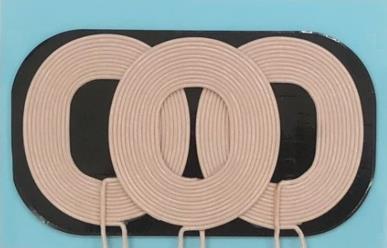
With no direct electrical connection between charger (Tx side) and the receive (Rx) device, power is transferred between the two sides via an H field created by electrical current flowing through the Tx coil. The Rx coil captures this H field and converts it to an electrical current through the Rx winding. The mechanism for this process is magnetic coupling and is impacted by alignment between the two coils (X and Y), the separation distance (Z gap) and the orientation (parallel). In an automotive application, orientation is controlled by the flat center console area surface. Alignment is addressed currently by a 3 distinct windings Tx coil and with built-in control intelligence, the Qi system determines which winding is best aligned. This 3 windings coil provides some positional freedom but only in one axis. An example of a MP-A9 coil is shown in Figure 2.
Click image to enlarge
Figure 2 - Standard WPC MP-A9 Tx Coil
This 3 windings coil is not a system requirement, but is the "norm". There are current efforts to have a 2 windings coil configuration for smaller vehicles to reduce both size and cost, with the trade-off being alignment and possibly reduced efficiency.
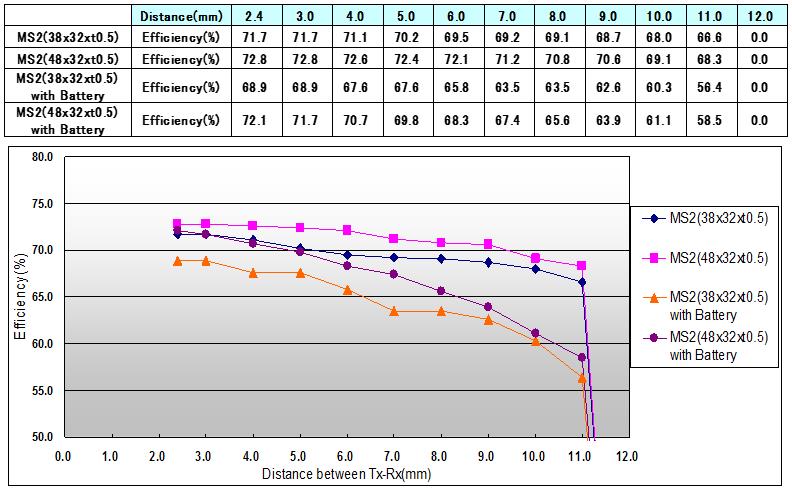
The Z direction gap is more of a challenge due to the original Qi standard specifying the maximum magnetic shield-shield distance as <5 mm, and not the coil winding-winding distance. The shields are used for: 1) shielding the H field from objects behind the coils, 2) shaping/directing/containing the H field, 3) helping to set the inductance values, and 4) providing the mechanism for magnetic coupling, a function of the distance between the two magnetic shields. Therefore, for in-vehicle applications, with a Rx coil winding thickness of up to 1.0 mm, a 1.0 mm phone back cover thickness, a phone protection case up to 3.0 mm and then a center console thickness of 2.0 mm, a Tx winding structure thickness of 2.5 mm, all means the actual shield-shield Z gap distance is 9-10 mm, which assumes no gap between the phone case and the center console. As the coupling factor decreases with Z gap distance, pressure is put unto the Tx side to compensate for the lower coupling by requiring more Tx input current to maintain the power required on the Rx side. Since the electrical load does not change, requiring more input current to maintain the same output power is another way of saying decreased efficiency. This is shown in Figure 3.
Click image to enlarge
Figure 3 - Efficiency Vs. Z Gap using WPC A11 Tx Coil, 5V Rx Output
This testing used two Rx coil sizes, with and without having a battery located behind the Rx coil. The efficiency rolls off as the Z gap increases between the coils. The Qi system also operates with in-band communication and when coupling (K) is low, communication may cease and stop power transmission. This was the case for the bottom orange curve so all testing was terminated at 11 mm. For Qi EPP systems, the higher currents will help with coupling, but it is important to understand what the real-world Z gap is.
Higher coil winding currents also create higher wire losses. There is both a coil's DC resistance (DCR) value and AC resistance (ACR or RAC) value, with wire loss being related to RAC and is shown in Equation 2.
PLOSS = I2 x RAC Eq.2
where:
I - Tx coil winding AC current
RAC - resistance at operating frequency
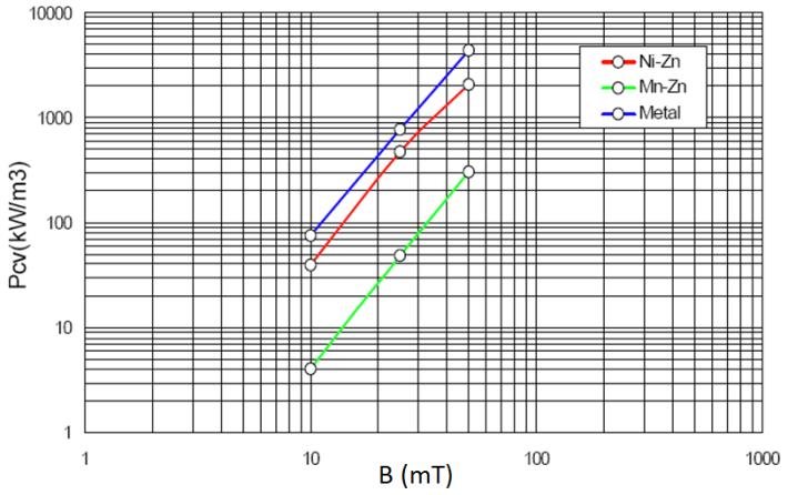
Higher current systems also generate more magnetic flux (φ) and higher core losses within the Tx coil magnetic shield. Typical curves, for various magnetic materials, are shown in Figure 4 for core loss (Pcv) versus magnetic flux density (B), with Ni-Zn and Mn-Zn being types of ferrite.
Click image to enlarge
Figure 4 - Magnetic Shield Core Loss vs. Magnetic Flux Density
Flux density is related to the magnetic field and is supplied by magnetic core suppliers in the material's B-H curve. The relationship between current and the H field is given in Equation 3.
H ∝ N x I Eq. 3
where,
N - the coil's number of winding pattern turns
I - Tx coil winding AC current
In wireless charging systems, the alignment and Z gap parameters cannot be controlled by the auto-maker. How and where the user places the handset into the console area, what type of protective case is used, internal Rx coil size and shape, whether the handset shifts during acceleration and braking, all will impact efficiency.
Efficiency - Tx Power Topology Factors
A key efficiency improving technique is to use a Push-Pull converter drive scheme. The Push-Pull converter supplies the Tx coil current by a set of switches in a synchronized timing scheme. The switches are alternately switched ON and OFF, thereby cycling the direction of the current through the coil during both halves of the switching cycle, unlike other topologies (e.g. Bucks) that rely on stored energy within passive devices to supply current during the switch's OFF period. Also implemented with Push-Pulls, is a short "dead" time with no current, ensuring both switches are not ON (sourcing current) at the same time which would cause damage to the supply. Overall, Push-Pull converters have steadier input current over other power topologies, generate less EMI noise, and are more efficient in higher power applications.
A technique also used is called Zero Voltage Switching (ZVS) or "soft" switching. In order to reduce losses during the turning ON/OFF of the switches, the system ensures that prior to the switching process, there is no voltage across the switch. This eliminates the possibility of having current flowing through the switch with an applied voltage. Having ZVS therefore reduces switching losses and substantially improves efficiency. Timing control is therefore a key requirement.
Another advantage of ZVS is it reduces harmonics. Reducing the harmonics assists in complying with the CISPR 25 requirements. This is included here as it also plays a key part in efficiency. In the Qi system, the Tx and Rx side circuits' L-C networks are tuned to a specific frequency. Harmonic energy is wasted as the tuned Rx circuit will rectify little energy outside of its tuned frequency range.
Thermal Issues
Losses in wireless power systems come from the circuit components, wires and cores on both the Tx and Rx sides, and coupling losses to bridge the air gap between the two coils. Within the auto-maker's control are only the Tx side wire, core and the circuit component losses, including the PCB, and all lead to increased temperature. Auto-makers have very stringent temperature rise limitations and is usually at +10oC rise over ambient temperature.
Magnetic core losses are dependent on the material's characteristics. The key parameters are: material type used, i.e., ferrite or powdered iron, the thickness of the shield, the operating frequency (creating inner-material losses), and the magnetic field flux density. Temperature can have an impact but limits set by the auto-makers have ensured that the temperature has no real impact on core losses.
For the Tx coil, multi-strand litz wire is used to reduce AC losses as the frequency increases, which are due to a phenomenon called "skin effect". Simply stated, as the frequency increases, more current flows closer (higher current density) to the wire's outer surface and utilizes less of the cross sectional area. This creates increased resistance, which increases wire loss and temperature rise. Litz wire creates much more overall wire surface area and helps reduce AC resistance over standard single strand wire. As the power and current requirement levels continue to go up, the need to use higher stand litz wire continues. Balancing performance, thermal issues, wire diameter and coil size then become key aspects of in-vehicle systems.
Taming the Beast
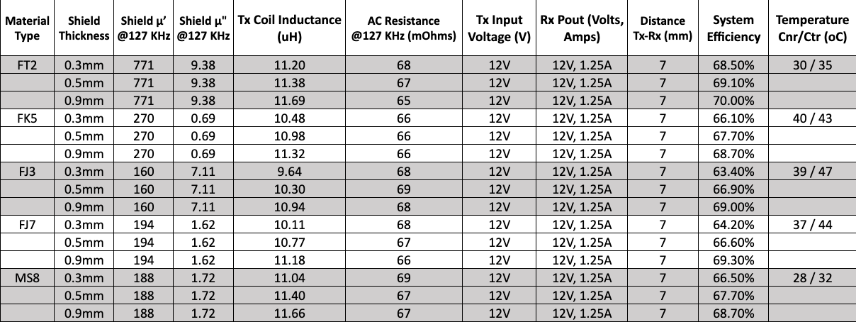
Using a Spark Connected 15W automotive Tx module aptly called the "Beast", which implements all of the aforementioned EMI suppression and efficiency improvement techniques. Testing was done comparing the Tx coil's shield material type and thickness. Four ferrite and one powdered iron based materials were tested and results were obtained for efficiency and thermal conditions. These are provided in Table 2.
Click image to enlarge
Table 2 - Tx Shield Material vs. Thickness vs. Efficiency Paired with a 50 mm x 40 mm, 8.22 uH Rx Coil
In the Temperature column, Tx shield corner (Cnr) and center (Ctr) measurements are provided for the worse-case scenario of a 0.3 mm thick shield and are for ambient + self-temperature rise values.
Regardless of the shielding material, all maximum efficiencies were for the thicker shields (with 3 sheets of 0.3 mm MS8 used). This also coincides with the thicker shields creating higher inductances which helps in the coupling factor through increased mutual inductance (Lm). Table 2 also shows that the higher µ' material, FT2, exhibits the highest efficiency across all thicknesses. There are other loss sources and system factors that come into play and the data does not address these. One of these is related to the Tx coil inductance. Since the resonant circuitry was tuned for the FT2 material and its initial inductance value, coupling will shift the inductance values and de-tuned the circuit and reduced efficiency. In design practice, attention would be given to re-tuning the circuit by adjusting capacitance.
As currents continue to increase for higher power applications, the magnetic flux density saturation (Bs) values of the shield materials need to be known. If saturation occurs, a percentage of the magnetic flux will escape out the back, reducing efficiency and causing additional heating via Eddy currents on any metal in close proximity.
Revisiting the plot in Figure 1, another EMI test was conducted by applying a metalized film over the Tx coil to help suppress low frequency harmonic spikes prevalent in the plot. The EMI suppression approach vastly improved the even numbered harmonics up through the 6th harmonic or 762 KHz. This new plot is shown in Figure 5. Needed still, is improvement in the 1-2 MHz range as the Quasi-Peak values are slightly above their limits in. However, the design was certified for Class 4.
Click image to enlarge
Figure 5 - CISPR 25 Class 5 Testing 100 KHz to 30 MHz with Metalized Film
What's Next for Vehicles
The Tx system makers have already begun preliminary design work in the 30-45W range, addressing tablets and lower power notebooks. The idea is that the in-vehicle Tx locations could be behind the headrests of the front seats or lower in the pouches for persons sitting in the back seats, allowing for continuous operation of the device being wirelessly powered or recharging of the battery.
Even though this power range is early in its development cycle, there is already early talk about increasing the power level up to 65-90W. With each step in power, the more critical the design becomes in addressing EMI, efficiency and thermals.
The author would like to thank:
1) The power gurus from Spark Connected, Ken Moore, Emanuel Stingu and Yulong Hou, for their knowledge and testing data for the "Beast".
2) National Technical Solutions, in Plano, TX, who performed the CISPR 25 testing.


