The gatekeeper of performance
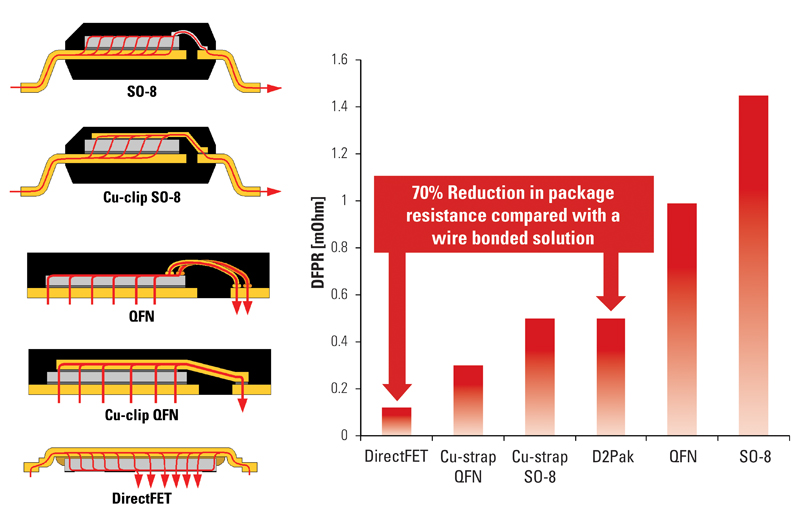
Figure 1: The Die Free package resistances of different power semiconductor packages
The 2011 automotive year started with the Detroit Auto show where the new Chrysler 300 was launched, its headline, a 3.6l V6 engine delivering a whopping 292 hp (218 kW), 41 hp (31 kW) more than the previous model year of the same car. Of course it will come as no surprise to learn that the old model was a smaller engine with a displacement of 3.5 Litres compared to the new 3.6 Litres. But what is surprising is that despite having a bigger, more powerful engine, the new vehicle delivers an 8% improvement in fuel economy over its predecessor. In a similar manner Ford announced that from 2012 its Escape/Kuga models will feature start-stop technology delivering a 10% improvement in efficiency. Meanwhile Hyundai Mobis debuted their new Gamma 1.6l engine, their smallest gasoline engine to feature direct injection (a technology traditionally limited to diesel cars) which they claim will deliver fuel economy of 40 mpg fractionally better than the 39 mph boasted by the new hybrid Honda CR-Z. The rapidly rising gasoline prices over the last few months clearly are making consumers hungry for fuel efficient cars. But perhaps more significant in driving the eco-car trend is that car manufactures need to sell more fuel efficient cars. A swathe of increasingly stringent emissions regulations is forcing car manufactures to release more fuel efficient cars and in some parts of the world they risk loosing profitability if they do not step up to the challenge. In Europe from 2012 car manufacturers will be fined if the average CO2 emissions of the new cars sold is more than a certain threshold. In the near term fines will be significant at around 5 - 15€ for every gram of CO2 per vehicle over the target, however this seems modest when compared to the alarmingly high 95€ per gram over target fine that will be imposed from 2019 onwards! Clearly fuel efficiency is not just fashionable; it is going to make business sense. One way to improve fuel economy and emissions is to move to hybrid and fully electric topologies. But the dominance of the internal combustion engine is unquestionably strong and for good reason. There is a highly establish refueling infrastructure, a refined and experienced servicing and repair network, the technology is well understood and relatively cheap to mass produce. But gasoline and the internal combustion engine also has another strength: power density. A car can only be so big or so heavy, with gasoline having an energy density of 45MJ/kg compared to 0.1MJ/Kg for a lead acid battery it is easy to see why a gasoline internal combustion engine makes such a compelling source of power for a car. To this end car manufactures are making improvements to this traditional power source to improve efficiency and system needing power semiconductors like electric fuel pumps, fuel injection and electric power steering are being widely adopted. With efficiency being a driving actor semiconductor companies need to continually offer better performance and traditionally the biggest challenge to advancing performance has been the semiconductor itself. But as the silicon becomes better we need to consider the rest of the chain and in particular the package which houses the silicon. A simple figure of merit when considering MOSFETs is the RDS(ON), a parameter which directly impacts the conduction losses of the system and ultimately its efficiency. This single value on the data sheet is comprised of two values, firstly the on resistance of the MOSFET die and secondly the resistance of the package, summed together these give the stated RDS(ON). In a D2Pak the package resistance can be as high as 0.5mOhm, this does not sound a lot, but considering that a state-of-the-art 40V MOSFET would have an RDS(ON) of around 1mOhm, its impressionable that around 50% of the RDS(ON) can be attributed solely to the package. To combat this various packages have been developed, one the more established being the DirectFET form International Rectifier which has a package resistance of around 150μOhm, or 70% less than a D2Pak (see figure 1).

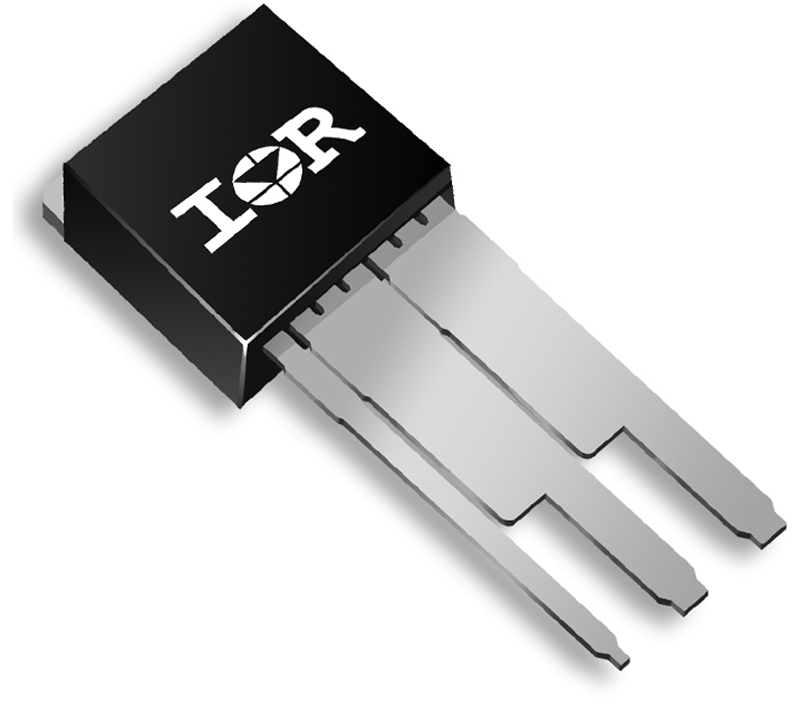
Clearly, as semiconductor performance becomes increasingly better, the role that the package plays becomes more and more important. We must not forget that the package is a series element in the system; all of the current must flow through the package and heat generated inside must flow out unrestricted. With the advent of high performance surface mount packages like the DirectFET system manufacturers can achieve higher power densities with the convenience of SMD manufacturing and assembly. But in some very high power systems there is still a need or indeed a preference for through-hole assemblies. Considering this and the fundamental values of DirectFET, International Rectifier took a fresh look at the established long-leaded cousin of the D2Pak, the TO-262 (figure 2a). It is not widely known that on the TO-262 package that the leads add significant resistance in addition to the RDS(ON) of the device. In fact the drain and source leads of a typical TO-262 have a total resistance of just under 1mOhm. Many years ago when the RDS(ON) of a MOSFET was in the 10mOhm range 1mOhm of extra resistance on the leads was insignificant. Today given improvements in silicon technology a 1 or 2mOhm MOSFET in a TO-262 is to be expected, so 1mOhm of lead resistance suddenly becomes very significant in the total drain to source on resistance of the device.
With an aim to improve the efficiency of the TO-262 package International Rectifier has developed and recently released the new WideLead TO-262 package. In terms of dimensions this package is identical to the traditional TO-262, but the leads are significantly wider. This has the benefit of reducing the total drain and source lead resistance from just under 1mOhm to around 0.5mOhm. Furthermore by enhancing the wire bonding used inside the package the RDS(ON) is also reduced by 20% compared to a traditional TO-262. The obvious benefit here (like the DirectFET) is that by reducing the package resistance conduction losses are reduced and indeed a smaller area of silicon can be used to achieve a total overall on resistance. A second and perhaps more significant advantages is that by reducing the lead resistance the joule heating or self heating which occurs when an electrical current flows is dramatically reduced. Figure 3b shows a thermal image of a standard TO-262, and next to it figure 3a showing the WideLead under the same electrical conditions; the WideLead is running cooler.
In looking at figure 4 is possible to see the significant difference in lead temperature between the two packages. At a current of 60A the lead temperature of the standard TO-262 is around 121°C, by comparison the WideLead is running almost 40% cooler at 74 °C. In fact the current in the WideLead can be increased to 80A before it reaches the same lead temperature which the standard TO-262 exhibited at only 60A, thereby handling 30% more current for at the same temperature point! The result is a package with lower conduction losses and lower self-heating. By running cooler the designer has more room to trade-off higher currents and power densities for a given operating temperature or indeed, make benefit of the lower conduction losses. Moreover running at a lower temperature only improves long term reliability and indeed might even allow a lower temperature substrate material to be used in some cases. With a compulsive need to go to increasing levels of efficiency on vehicles through power electronics it's vital that the new electronic systems deliver on efficiency, reliability and power density. Advanced silicon technologies and new semiconductor materials like Gallium Nitride will only put more pressure on the package; today's gatekeeper of performance. Simultaneous innovation on both the semiconductor and package fronts will however ensure the gate remains open. www.irf.com


.jpeg)
 Single.jpeg)
