Current-sense amplifiers (CSAs) are gaining popularity in sensing currents across a multitude of applications
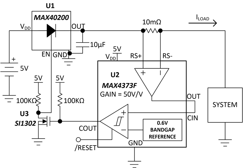
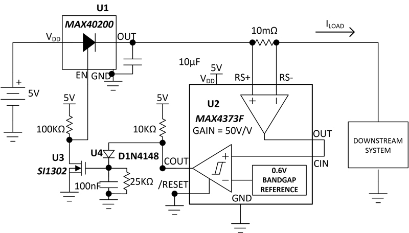
Figure 1. Schematic showing current sensing and short-circuit protection.
In today’s battery-operated mobile devices, two of the most important aspects are battery life and safe operation. In other words, end users expect long battery life, and the battery should be guarded against overheating from over-current drain due to undesired faults.
A CSA can monitor current out of the battery and detect current over drain beyond a predefined threshold. Current sensing is useful to monitor battery current drain by load.
In applications where current sensing isn’t required, isolating the power path from battery to load is paramount in case of battery short-circuit to ground. A diode forward-biased with respect to battery to load can block reverse voltages, but it cannot block forward voltages and currents in case of a battery short-circuit to ground.
A diode that could be enabled and disabled based on the amount of current drain from the battery provides a useful safeguard in these battery-powered applications.
Example Current-Sensing and Smart Fuse Design
To illustrate our points, we will highlight an example design based on an ideal diode and a current-sense supervisor.
The ideal diode features reverse battery protection and saves power as it drops very little voltage on the order of tens of mV, an order of magnitude better compared to Schottky diodes. To be precise, when forward biased and enabled, an ideal diode drops about 43mV for a 500mA load and about 85mV at 1A load. It has a shutdown mode that disables the device and blocks rails up to 6V by disabling the current path from source to load.
The current-sense supervisor has a CSA with internal bandgap reference and a latch comparator. A threshold comparator with latch input working in tandem with the current-sensing device enables fault detection and protects the downstream electronic circuitry by disabling the battery drain.
As shown in Figure 1, U2 (CSA) is monitoring current flow into a variable load. The output of the CSA is presented to the input of the threshold comparator.
The threshold voltage, or output of the CSA, is set by the internal gain of the amplifier (50V/V) and the choice of the sense resistor (RSENSE in this case is 10mΩ). If the load current increases, the output of the CSA tied to the comparator non-inverting input approaches the threshold voltage of 0.6V on the inverting input.
The output voltage of the CSA from Figure 1 is given as:
OUT = ILOAD*RSENSE*Gain = ILOAD*10mΩ*50V/V
Where: OUT is output of the CSA
ILOAD is the load current consumed
The load current at which the fault must trigger is at:
ILOAD = [CIN Threshold/CSA Gain]/RSENSE = [0.6V/50]/10mΩ = 1.2 Ampere
Where: CIN threshold is the voltage above which the comparator output will trigger from high to low
Choosing RSENSE would set the value of the load current where the fault triggers.
From Figure 1, ideal diode U1 is enabling the battery to supply current into the load. Current above 1.2A from the battery into the load is set as the over-current drain threshold. When current being drained is >1.2A, the comparator in U2 will pull the EN (enable) pin of U1 low, which in turn isolates the power path from battery to load.
The comparator internal to U2 is a latch enable comparator with its negative input internally connected to a 0.6V band gap voltage reference. When /RESET pin on the comparator is driven high, the internal latch is active, and once CIN rises above 0.6V, the output goes high and latches into an open drain OFF state that remains in this state even if CIN drops below 0.6V.
Voltage on CIN rises above 0.6V for a load current >1.2A in Figure 1, and once COUT goes high, the user must manually apply a low signal on its /RESET pin for the circuit to go back to normal functional mode if the current is less than the over-current threshold. If short-circuit/fault prevails, the circuit keeps going back to shutdown mode after every attempt to drive the /RESET pin low.
The results presented below are broken down into three scenarios from the schematic in Figure 1:
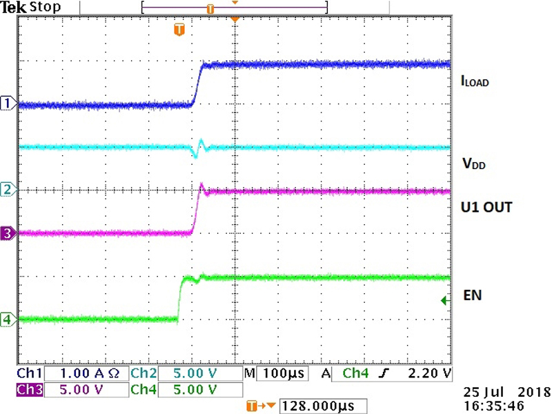
1. Normal operation is shown when load current is less than 1.2A, i.e., the current threshold below which U1 is enabled and load current needs to be kept ON. CH1 on the scope plot below is ILOAD (load current) through the diode (U1) from the schematic into the variable resistor load, CH2 is input voltage on the U1 VDD, CH3 is output voltage on the U1, and CH4 is the enable signal on the EN pin of U1.
From CH1 on the scope plot in Figure 2, given that load current is ~1A (<1.2A), enable goes high when the system is powered ON, enabling the current path from battery into load. As can be seen, once the enable signal comes on, VOUT of the U1 comes in at about 40µsec, which is the enable time of U1.
Click image to enlarge
Figure 2. System behavior with trigger on the enable pin of U1 with load current <1.2A.
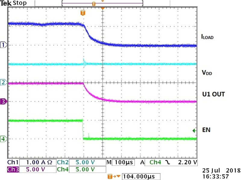
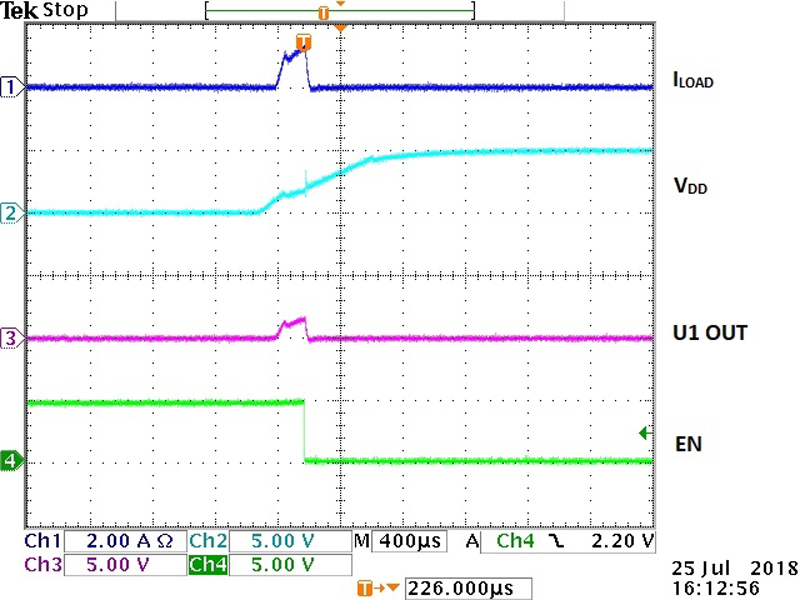
2. 1.2A over-current high threshold is detected and, subsequently, the load current path is turned OFF.
Figure 3 outlines the turn OFF response of the system. Figure 3 shows that ILOAD has hit the 1.2A threshold that was set, and the system automatically pulls the enable signal low, which, in turn, brings both output voltage and load current of the U1 to zero. The slow response (~120µs) in both ILOAD and VOUT is due to 10µF on OUT pin of the U1. A smaller capacitive load can be used to improve response time of the shutdown functionality.
The comparator output enables pulling the EN pin low. As a result, the whole system turns OFF when >1.2A is detected. Since this is a latch comparator, the user must manually provide a low signal on the /RESET pin to be able to get the system back up and running after this over-current event. If the ILOAD>1.2A prevails when the /RESET pin is driven low, the same as shown in Figure 3 repeats.
Click image to enlarge
Figure 3. System behavior with trigger on enable pin of U1 with load current >1.2A.
3. Short-circuit detected in the system when the load is shorted to ground via 0Ω on power-up.
Figure 4 below shows the system response when there is a short-to-ground present upon power-up of the system. In this case, a 5V battery could source 5A of current in a short-circuit condition. However, as soon as ILOAD is >1.2A, enable is pulled low to disable the power path with VIN and VOUT completely isolated. On CH1 it is shown that it takes about 80µsec for ILOAD to settle from 1.2A to 0A.
Click image to enlarge
Figure 4. System behavior of the output of U1 short-to-ground with 5A short-circuit load.
Expected Output Voltage Error
Output voltage error expected from the sensing current through the shunt resistor is 0.3% to 5% depending on the sense voltage drop across the sense resistor. The input offset voltage of the CSA is the bottleneck to measure the small signal differential voltage on the order of the input offset voltage across its inputs.
The higher the load current, the higher the sense voltage drops across inputs of CSA and, hence, the lower the output voltage error. At the high end, with 1.2A load current, total output voltage error is around 0.3% as the sense voltage drop across the sense resistor is on the order of a full-scale sense voltage.
From Figure 4, It takes about 80µsec to isolate the battery from the load in the event of a short-circuit to ground.
Overcoming Manual RESET
A timed auto-reset function can be beneficial in some cases, such as the scenario we’ll discuss here. In the event of a fault (short-circuit condition) as shown in Figure 5, the EN input to U1 is immediately pulled low. The circuit waits for 1msec with R=10KΩ, C=100nF, and diode U4 combination, and attempts to re-activate the EN input. If the fault persists, it goes low again. This circuit tries to enable the pass device every 1ms and, if the fault condition is no longer present, normal operation resumes.
No fault condition will have the output of the comparator at low, or the gate of the U3 FET at low pulling the EN input of U1 high. In the event of a fault (short-circuit or beyond specified load pull), the output of the comparator is high, with the FET turned on and the drain of the FET pulled low. EN input pulled low disables the U1 and, as a result, cuts the supply source to the downstream circuitry at fault. In the absence of the fault, the output of the monitoring comparator is low again, discharging the gate of the FET until V(GATE) < VGS(TURN ON) , turning off the FET and pulling EN high again. This condition continues until the fault persists.
A fault condition is not a good sign, considering safety and device violations. But random instantaneous events like unwanted coupling or manual/human error can create such scenarios, and we may need the design to be smart and understand such events. The automatic reset is useful in such cases.
Click image to enlarge
Figure 5. Timed fuse circuit to re-enable U1 automatically.
Conclusion
This article outlined how over-current drain beyond a threshold from the battery is sensed and stopped at the same time. Three different scenarios were presented as per Figures 2, 3, and 4, respectively, in terms of system response for three different current drain ranges. Figure 2 provides the power-up response when the load current is less than the over-current threshold of 1.2A, while Figure 3 provides shutdown response when the load current is >=1.2A and Figure 4 provides the power-up short-circuit response.
For scenarios where providing a manual reset is an issue, a timed fuse circuit was presented in Figure 5 to have automatic control for re-enabling battery drain in 1msec as soon as current drain is less than the over-current threshold of <1.2A.
Maxim Integrated