Power Supplies: Designing with Magnetic Components
Experienced power-supply designers know that the success or failure of their designs depends heavily on the proper selection of magnetic components
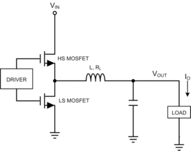
Figure 1: Buck converter
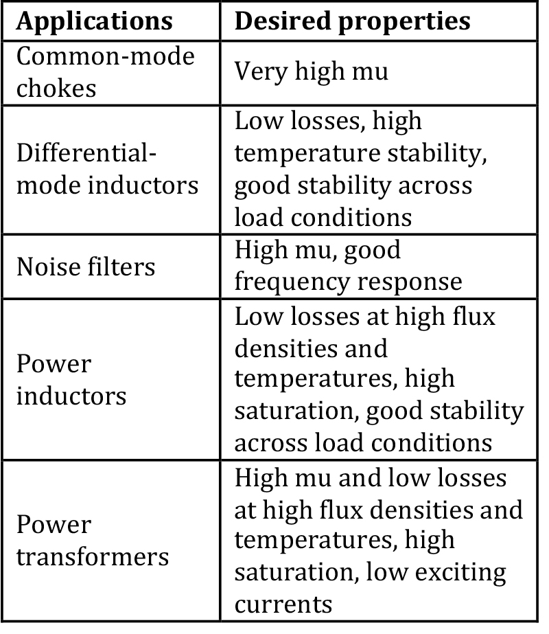
Magnetics play an important role in power supplies; they can be used as elements in power conversion and filtering. Experienced power-supply designers know that the success or failure of their designs depends heavily on the proper selection of magnetic components. Since magnetics can be used in a wide range of applications, it is good to know the basic characteristics that make it suitable for each one. The desired properties for some application types are shown in Table 1.
This article will focus on power inductors in a typical buck converter application. For power designs, the inductor's saturation level is critical. Saturation level is typically defined as the DC current level at which the device's inductance declines to 70% of its nominal inductance. The DC current can saturate the inductor quickly if an air gap is not introduced into the core's magnetic path. Depending on the type of material used air gap structures vary and the primary objective of the air gap is to tailor the saturation curves. Powdered iron materials have an inherent air gap distributed throughout the core, which gives them a soft saturation curve. Ferrite material must have an air gap physically inserted or ground between the mating surfaces of the core halves. Typically the saturation curve is steeper for ferrite materials; hence the introduction of the air gap is critical.
Click image to enlarge
Table 1: Desired properties for some common applications of magnetics
The next important criterion is the root-mean-square (RMS) current rating of the inductor, defined as the current at which the inductor’s temperature rises by 40°C.
High-performance buck converters operate at high switching frequencies enabling high bandwidth loops in order to get a fast transient response. This helps designers to use smaller output capacitors. As a result, the most popular inductance values are between 0.1 µH and 1.5 µH, with peak currents pushing to 30 A and ripple currents rising to 40% and higher. Under these conditions, core losses become a significant factor in inductor selection.
Most magnetics design guides recommend a core-to-copper loss distribution of at least 50-50, but 30-70 is actually preferable. It is easier to dissipate the heat from the winding versus the core material, as copper has a higher thermal conductivity than either ferrite or powdered iron.
Core losses are a function of frequency and flux swing, and are defined in Equation 1:
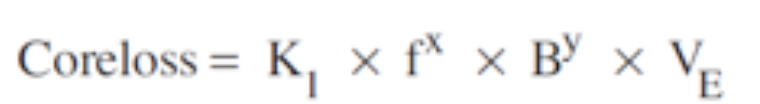
where K1 is a constant of the core material, f is the switching frequency in kilohertz, B is the flux density in Gauss, x is the frequency exponent given for a specific core material, y is the flux component given for a specific core material and VE is the effective core volume in cubic centimeters.
Core loss will vary with the swing in flux density, frequency and temperature. Core volume is also an important factor, and larger-sized inductors with the same material type will have lower core losses.
Let’s look at a buck converter and the associated factors affecting core and copper losses in the inductor. Figure 1 shows the basic building blocks of a buck converter.
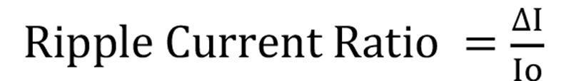
Equation 2a and 2bshows the formula for inductor selection in a buck converter, it also introduces the term ripple current ratio which is the ratio of peak to peak ripple current (ΔI) in the inductor to the output current (Io).
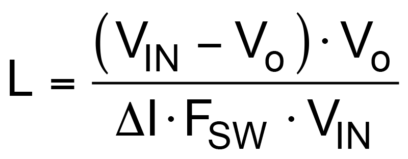
It’s typical practice to select a ripple current of about 30% to 40% of the converter’s full load current. From Equation 2, you can see an inverse relationship between switching frequency and inductor value, implying that you can reduce the switching frequency to improve efficiency and choose a larger inductor value to keep the same ripple current.
Unfortunately, there are several trade-offs that get in the way.
First, a larger inductor value means a physically larger inductor, which would increase printed circuit board area. More importantly, a larger inductor value will require more turns on the core. More wire in the inductor means more DC resistance for a given physical size. The increased DC resistance will produce more losses and lower the efficiency.
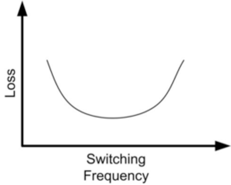
There will usually be an optimum switching frequency that will provide the lowest losses. As you change the frequency, you adjust the size of the inductor to keep the same ΔI. At high frequencies, the switching losses will increase; at low frequencies, the inductor will get larger and produce more losses from DC resistance. You’ll end up with a curve like the one shown in Figure 2.
Click image to enlarge
Figure 2: Variation of losses in an inductor with switching frequency
The core losses of the inductor will also depend on switching frequency, sometimes in a complex way, but always increasing with frequency. The type of core material plays a large role in core losses. Typically, a powdered-iron core will have more loss at switching frequencies greater than about 1 MHz compared to a ferrite-type core. The best way to estimate inductor core loss is to use the graphs or calculators on the inductor manufacturer’s website.
Carefully choosing the switching frequency and inductor will go a long way toward achieving the lowest overall losses. Setting the switching losses equal to the conduction losses is a popular approach that provides good results in the majority of cases. This can also be your approach when optimizing the switching frequency for the converter even though other factors do influence the choice of switching frequency, such as the desired bandwidth of the converter.
Once the switching frequency is finalized, you need to size the inductor. The key factors to look for here are the ripple current and ripple current ratio, as shown in Equation 2.
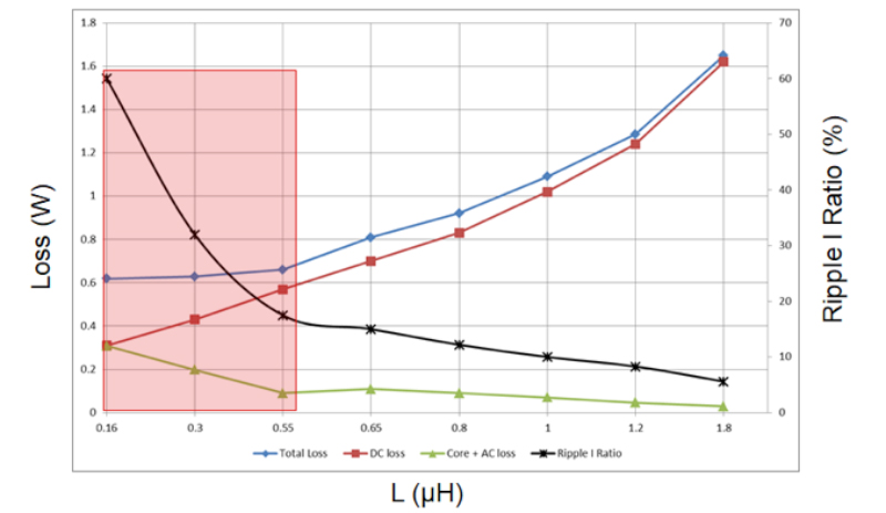
Let’s look at an inductor from Coilcraft to determine if there is an optimal ripple current ratio (Figure 3). You can see that there is an optimal ripple current ratio range shown in the shaded box. The total loss in the inductor stays relatively flat for a range of ripple current ratios from 60% to 20%. The trade-off is evident looking at the curves. Too-low ripple current ratios/higher inductance values translate to higher DC resistance losses. Too-high ripple current ratios/lower inductance values translate to higher core-plus-AC losses. The data also validates that the core-copper loss distribution of around 30-70 holds true for keeping total losses low.
Click image to enlarge
Figure 3: Coilcraft XAL7070 series inductor used in a buck converter operating at 500 kHz. VIN = 12 V, Vo = 1 V and IOUT = 20 A
Another thing you can infer from Figure 3 is that the XAL7070 has good core-loss characteristics. Even though it operates at a 60% ripple current ratio, its core-plus-AC losses are low. Good ferrite material translates to low core losses, and low skin effect loss translates to low AC losses. The shaded region may vary based on inductor selection; thus, the generic rule of thumb to keep the ripple current ratio around 30% to 40%.
Manufacturers like Coilcraft and Wurth have core-plus-AC loss calculators on their websites, which make it easier to determine the optimal inductor value for a specific application.
So apart from the choices in inductor size, RMS current rating and saturation current rating, you also need to pay attention to ripple current ratios, DC losses and core-plus-AC losses to optimize a converter for the best efficiency and keep the inductor cool.
Texas Instruments


