Each 5G installation requires a range of power conversion stages for RF amplifiers and data processing with requirements for reliability and performance
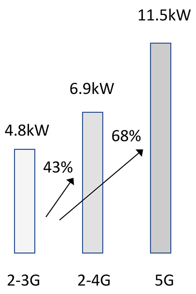
Figure 1: Base station energy consumption rise (adapted from Huawei data)
We have all been looking forward to 5G mobile communications and the promised benefits – faster downloads at speeds theoretically greater than 50Gps, 50x lower latency than 4G, the opening up of the IoT for home and factory automation and of course control of autonomous vehicles. By 2025, the resulting data traffic is predicted to be around 160 exabytes globally, according to an Ericsson mobility report, and with connected devices set to exceed one million per square kilometre, many of them in motion, providing adequate coverage is a major concern for the future. Traditional high-power base stations can leave ‘black spots’ with no signal, and, with the higher frequencies utilised in 5G, currently around 4GHz, the problem is potentially worse due to the shorter effective range. As the spectrum opens up, frequencies will get higher still into the millimetre wave bands and the only practical solution to better coverage is a network of lower power ‘micro’ cells covering smaller areas, fitted, for example, on utility poles or indoors in offices and public buildings.
All this means a vast expansion of equipment deployed and an increase in the electrical power it needs; 5G is expected to require twice or more power than a typical 4G base station. This increase, along with the expansion of the network, means operators are facing large increases in their energy consumption with a corresponding financial cost and global environmental impact. There is therefore intense pressure to make base stations, macro to micro, as energy efficient as possible. Additionally, higher efficiency leads to smaller and lighter equipment that is easier to install and maintain, in the ideal case requiring just one person.
Powering RF amplifiers efficiently
Base station RF output power varies widely from ‘femto’ cells operating at milliwatt levels to ’small’ cells typically up to 10W, to a little over 100W for the largest 5G MIMO (Multiple Input Multiple Output) array. RF power amplifiers (PA) at GHz frequencies are inherently not very efficient, typically 50-60%, so the PA alone can consume around 250W. This figure is for one amplifier, and in a typical 5G base station site, according to Huawei, the total power consumption can be over 11.5kW including legacy 2/3/4G radios and all of the data processing and control circuitry (Figure 1).
Addressing the power requirements for power amplifiers specifically, voltage rails need to be low-noise and tightly controlled, although downstream ‘envelope tracking’ may be implemented for increased amplifier efficiency. LDMOS power transistors are used up to around 4GHz and capable of kW power levels, requiring typically 26-32V supply, and for higher frequencies Gallium Nitride (GaN) devices are set to dominate with a rail of 50-60V, with power capability to hundreds of watts at better efficiency than LDMOS. These voltages are generated from isolated DC-DC converters powered from a system 48V rail with battery back-up.
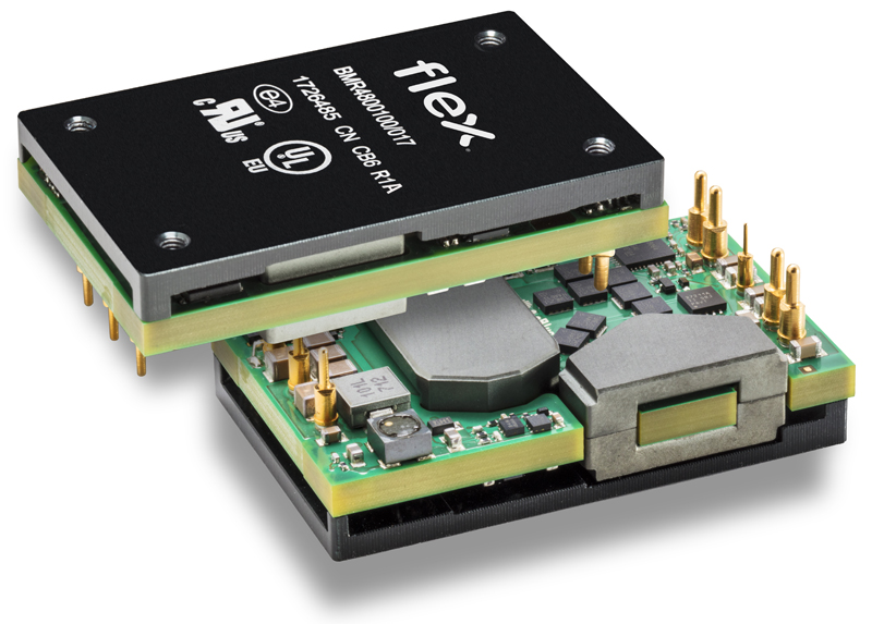
DC-DC converters with the typical ‘telecom’ input range are suitable and would often be in the baseplate-cooled ’brick’ format which suits the application environment – the RF power amplifier is typically at the antenna head in a sealed box with only conduction-cooling through the housing to the outside air. In the range of installations possible, the electronics might need to start up at sub-zero temperatures and operate at full power with the housing in full sunlight. To cope with these extremes, the RF PA with its power supply and control circuitry might need to be specified to operate at 85°C. Fortunately, most baseplate-cooled DC-DC converters are rated for at least this temperature, or considerably higher with derating, and best-in-class devices can achieve efficiencies better than 95%, contributing little to internal temperature rise (Figure 2).
Click image to enlarge
Figure 2: Baseplate-cooled DC-DC converters suit RF power amplifier power requirements (courtesy Flex Power Modules)
It is still important however that the converters are operated with a good margin away from their maximum ratings, as reliability and lifetime are key to the metrics of availability and total cost of ownership – it can be very expensive in terms of lost traffic and replacement cost if any electronics fails in a sealed enclosure at the top of a mast. To this end, at least ‘five nines’ availability is demanded, that is, 99.999% or a down time of less than 5.26 minutes per year. Given the complexity of the electronics in total, components and modules must have very high reliability figures individually, and a DC-DC converter with tens of millions of hours mean time between failures (MTBF) and 10+ years lifetime at high average temperatures would be the minimum expected.
Confidence in availability is enhanced when power rails are monitored remotely. If DC-DC converters are paralleled for redundancy, health monitoring is a necessity and ‘brick’ converters will often facilitate this with a digital power management interface, typically to the PMBus standard over I2C. As well as monitoring voltage levels, output load and temperature, PMBus will also allow adjustment of warning and shutdown threshold levels. Output voltage can be trimmed, often over a wide range, to suit RF PA requirements and allow technology upgrades without necessarily changing out the DC-DC converter. Some DC-DCs will also sense the load conditions and adjust their internal loop compensation for optimum load transient response. Dynamic adjustment of the output voltage is sometimes possible through PMBus, but not at the rate required for envelope tracking schemes, which need to follow amplitude modulation of the RF output at tens of MHz rates.
A base station is an intensive data processing system
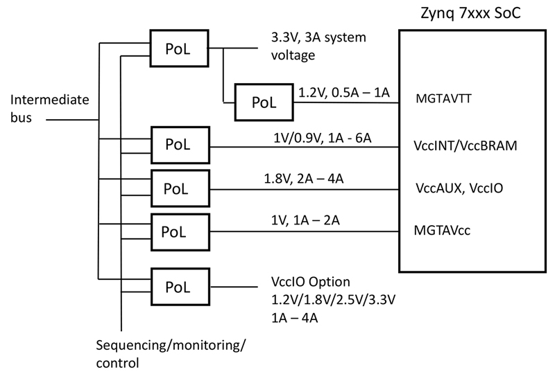
Up to the radio power amplifier and receiver stage, the electronics in a base station is typical of a data processing system comprising CPUs, FPGAs, SoCs, ADCs, DACs and a host of other logic and interface functions. These require a range of power rails from sub-1V to perhaps 12V or even higher for storage and interfaces and again DC-DCs are utilised, often in the familiar form of Point of Load (PoL) converters. PoLs are powered from an intermediate bus at 48V or 12V and provide tightly regulated voltage rails close to the target load. Figure 3 shows a typical arrangement for a Xilinx SoC device.
Click image to enlarge
Figure 3: Various power rails required for a typical SoC device
In legacy architectures of cell sites, the control electronics would be in a ‘hut’ close to the tower with a relatively benign environment, perhaps even air-conditioned. However, with the high cell density of 5G, a ‘zero footprint’ architecture is common, with all control, transport, baseband and power (CTBP) functions within a smaller ‘pole’ assembly. Located this way, electronics is exposed far more to temperature extremes and lightning strike effects and must therefore be appropriately protected to maintain reliability. In the application, any modular power converters such as isolated DC-DCs or PoLs should be the best quality with suitable derating and ideally with digital interfaces for control and health indication. This said, with small cells being very hardware cost-sensitive, DC-DC modules may be perceived as an expensive option compared with a dedicated discrete design. However, DC-DC manufacturers have responded with ‘stripped down’ low-cost products which are far more competitive and confer all the advantages of a quick, pre-tested, ‘fit-and-forget’ solution, while also taking up 50% less space on the board, producing less heat and enabling a fast time to market.
AC-DC power supplies are in the mix
AC-DC power supplies are required in all base stations as a primary energy source and to charge the back-up batteries. The AC source could be three-phase for larger installations, single phase 230VAC or even 277VAC for small cells powered from a lighting circuit using the phase to neutral voltage in a 480VAC three-phase system. Even with battery back-up, reliability is vital in all cases to avoid the cost of replacement in remote locations, so high-quality parts are necessary with in-built health monitoring. The converters are subject to all the variations of electrical and physical environment mentioned and baseplate-cooling of the AC-DC is often an advantage to avoid high internal temperature rises. This also removes the need for a fan with its inherent limited lifetime. AC-DCs must naturally have well-controlled noise emissions to avoid interference with the receiver signals.
Conclusion
5G cell hardware has to meet harsh environmental specifications with high performance and availability, at low total cost of ownership including acquisition, maintenance and energy draw. Power supply arrangements are fundamental to meeting these requirements and suitable isolated DC-DC converters, PoL modules and AC-DC power supplies from leading manufacturers can be selected from the ranges available from Avnet Abacus.