AC/DC power trends enabling high efficiency and dynamic power for AI-driven systems
Introduction
Large language models are revolutionizing how we access data and artificial intelligence (AI) advancements are disrupting how industries and societies use data center computing resources. Instead of typing keywords into a search engine, we are at the point where we can ask AI a question, much like we would ask a person, and get a detailed response. This represents just the beginning of what AI can do. AI now also writes code, generates pictures and videos, and transcribes and summarizes meetings. All of these AI functions require significant increases in power to enable them.
Click image to enlarge
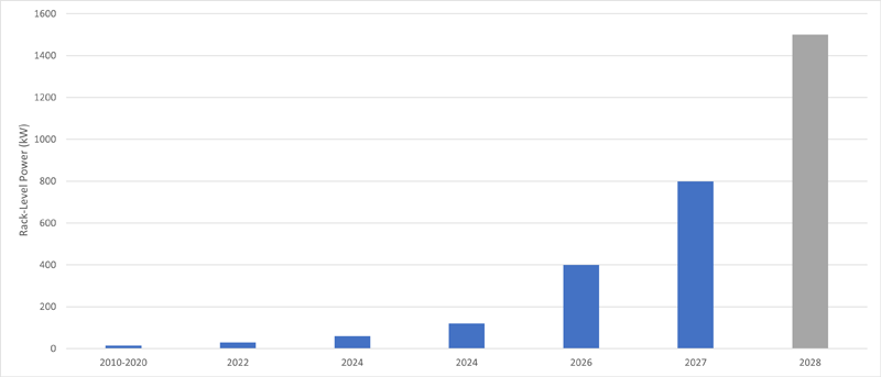
Figure 1: Rack-level power requirements
Figure 1 shows the IT server rack-level power requirements over time. The figure projects that by 2028, an IT rack will need 1.5MW of power, which is 10 times more power than what server racks are using today.
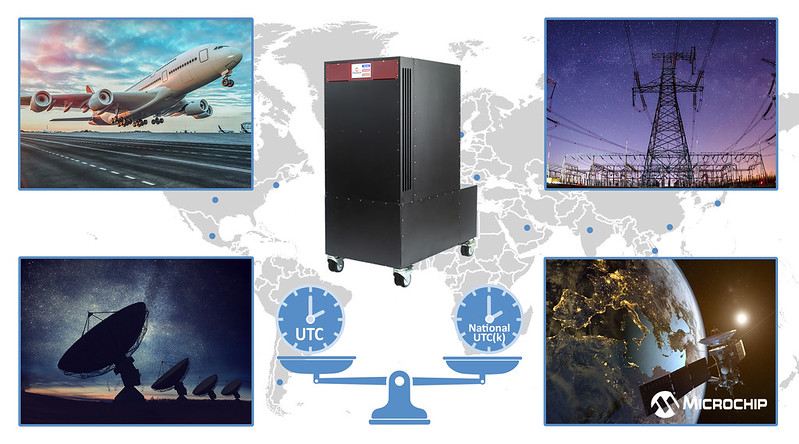
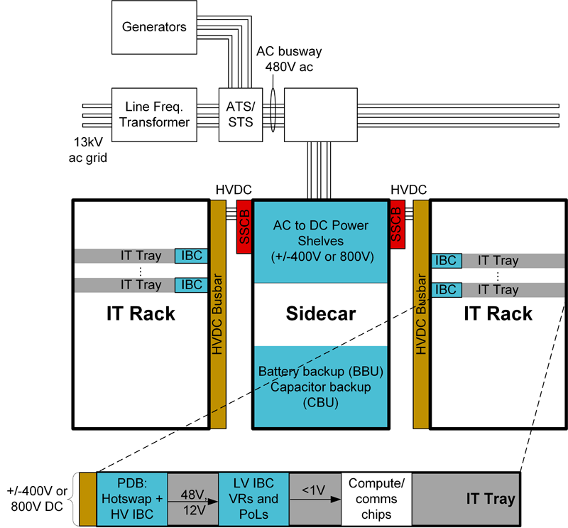
Figure 2 shows the first major evolutionary step in power delivery designed to support these high-power levels: the introduction of the sidecar. The sidecar maximized space in the IT rack for computing functions and to increase the efficiency of the power delivery to the IT rack. The sidecar contains support peripherals for the computing functions in the IT rack. One peripheral is the power supply unit (PSU), which is part of the power shelf. The PSU draws power from the three-phase AC power lines to create the high-voltage DC bus that powers the intermediate bus converters (IBC) inside the IT rack. This article describes innovative technologies used to create these PSUs.
Click image to enlarge
Figure 2: A third-generation AI computing DC distribution sidecar
AC/DC High-Voltage DC Requirements
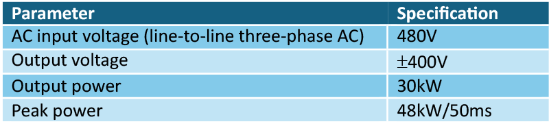
Table 1 lists the target requirements for the power supply this article discusses. The Open Compute Project provides more detailed requirements for additional use cases in reference [1].
Click image to enlarge
Table 1: AC/DC 800V DC power-supply unit requirement
The third-generation architecture shown in Figure 2 changes the input source from single-phase AC to three-phase AC to accommodate the rapidly increasing power demands. Each PSU on the power shelf requires approximately 30kW of output power to meet high-voltage DC PSU system requirements. Beyond dramatic increase in steady-state power, the power supply also must support large load transients.
Table 1 shows a load step of 160% for 50ms. However, reference [1] also describes a broader range of transient scenarios reaching as high as 175%.
Power-supply architecture
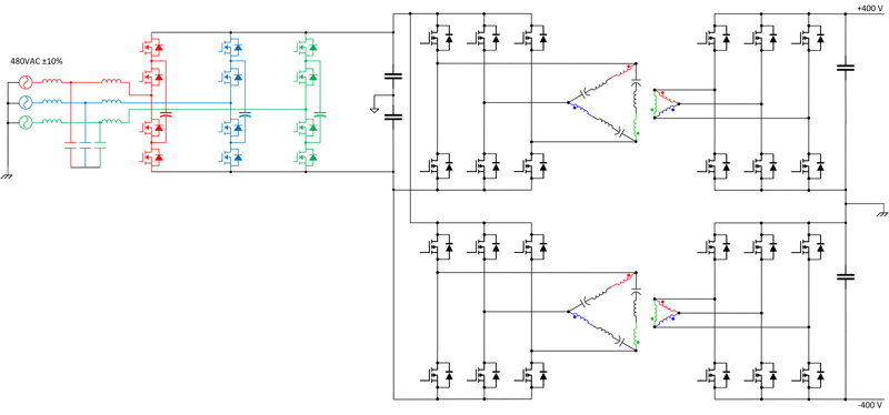
Figure 3 shows a system-level schematic of the AC/DC power supply suitable for use in a 3rd generation power distribution system. This power supply converts power from the AC grid and produces an 800V differential output voltage.
Click image to enlarge
Figure 3: AC to HV-DC power supply for the side-car
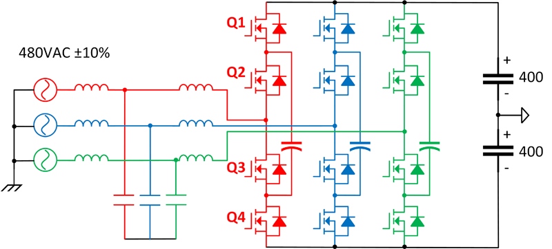
The power supply of Figure 3 has two stages. The first stage is the AC/DC stage (Figure 4) for converting power from three-phase AC grid. The proposed topology used is a three-level flying capacitor (3LFC) power factor correction (PFC).
Click image to enlarge
Figure 4: Three-phase, three-level flying capacitor topology
This topology uses four FETs for each AC phase. When designers control the voltage across the flying capacitors so that they equal to half the output voltage (400V in this case), each one of the 12 FETs in the topology needs to support half the output voltage. This voltage reduction provides significant benefits, since lower-voltage transistor stress opens the door for better cost-per-performance characteristics and provides access to high performance gallium nitride (GaN) devices.
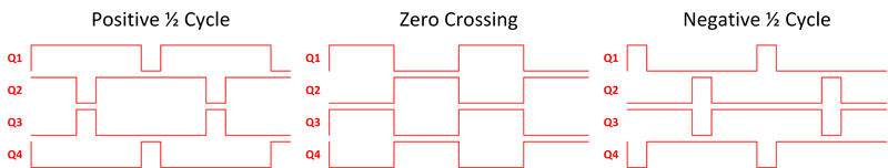
Figure 5 shows a series of pulse-width modulation (PWM) patterns for one phase of the topology during the positive half cycle, zero crossing and the negative half cycle. When the input voltage is positive, the duty cycle of Q1 and Q2 exceeds 50%; when the input is negative, the duty cycle falls below 50%. A 50% duty cycle is equivalent to zero. Interleaving the control of the switch pairs Q1/Q4 and Q2/Q3 doubles the switching frequency that the inductor sees reducing the inductor size. A smaller inductor value makes it possible to increase efficiency and reduce the physical size of the inductors.
Click image to enlarge
Figure 5: Flying capacitor FET PWM pattern
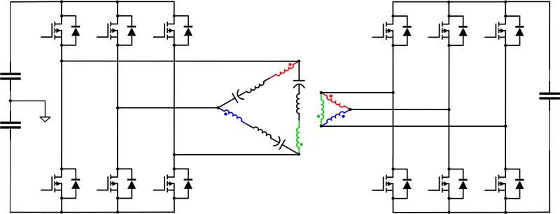
Since the PFC output is not isolated from the AC mains, you’ll need an additional stage with isolation. This isolation stage prevents circulating currents from flowing between paralleled modules, provides surge protection and can reduce creepage and clearance requirements for downstream equipment. The isolation stage also provides energy holdup and AC input current smoothing. A strong topology option for this stage is the three-phase inductor-inductor-capacitor (LLC) converter (Figure 6).
This topology features three half-bridges on the primary and secondary connected to the LLC resonant tank in a delta Δ configuration. Two technical considerations drove the delta-to-delta connection choice over alternatives: using the transformer leakage inductance as the resonant inductor and minimizing the root-mean-square (RMS) currents in the LLC tank elements. The delta connection reduces the RMS currents by a factor of √3 compared to the wye connection. Additionally, the delta connected primary puts the resonant inductor in series with the transformer winding, facilitating integration into the transformer. Reference [2] provides more detail about additional connection options.
Click image to enlarge
Figure 6: A three-phase LLC converter
To accommodate the large, fast transient load demands of AI processing, the LLC converter needs a control algorithm that can minimize the transient output voltage while keeping the output capacitance small. Hybrid hysteretic control (HHC) controls the voltage ripple across the resonant capacitor, enabling the control loop to respond to transient events faster while simultaneously maintaining excellent stability margin [3]. This high bandwidth control system works by summing charge control and direct frequency controlled (DFC) to improve transient response and stability margins.
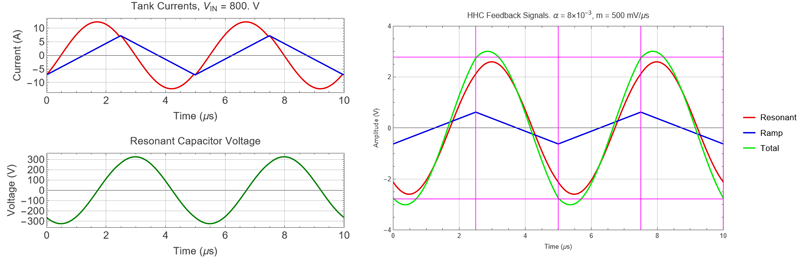
The HHC achieves this by creating a pulse width modulator that is the sum of a ramp with a slope “m” and a portion of the resonant capacitor voltage, α. Figure 7 shows the system waveforms and feedback control signals for an HHC control loop. The plots on the left of Figure 7 show the resonant tank currents in blue and red and the resonant capacitor voltage in green.
The plots on the right of Figure 7 show the control signals. The blue line is the voltage ramp injected into the system for DFC. The slope of the ramp used in this example is m=100 mV/μs. The red trace is the portion of the resonant capacitor voltage that is feedback for control, α=8×10^(-3). The green signal is m+α. The upper pink horizontal line is the upper comparator trip point. When the green trace goes above this level the upper FET turns off and the lower FET turns on. The lower horizontal pink line is the lower comparator trip point. When the green signal goes below this the lower FET turns off and the upper FET turns on.
Click image to enlarge
Figure 7: HHC Feedback Control Signals
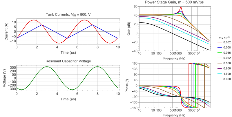
Figure 8 shows the loop dynamics of an HHC-controlled system compared to a traditional DFC system. The bode plots to the right show the plant gain and phase as a function of the resonant capacitor voltage feedback ratio α. Notice that when α is very small (i.e. the red curve) the plant gain is 2nd order with 180° of phase shift. This is roughly equivalent to a DFC system. As α becomes larger the system becomes more charge controlled, and the loop dynamics change from a 2nd order system to a 1st order system. This first order behavior dramatically increases the stability of the system while at the same time allowing the loop dynamics to achieve the higher bandwidths required to support AI load dynamics.
Click image to enlarge
Figure 8: HHC vs. DFC loop dynamics
Conclusion
AI is completely changing the way IT rack power supplies are delivering power. The voltages, power levels and transient requirements require a new approach to designing these power supplies. A two-stage approach enables robust AC line current management, hold up and high-performance load transient response. The flying capacitor PFC and three-phase LLC with HHC are just two examples of novel approaches to solving these problems.
References
1. “Diablo 400 Project: Rack and Power,” v. 0.5.2. Open Compute Project: Austin, Texas, May 30, 2025.
2. Gadelrab, Rimon. 2023. “PCB-Based Heterogeneous Integration of LLC Converters.” Ph.D. dissertation, Virginia Polytechnic Institute and State University.
3. “Improving Transient Response in LLC Converters Using Hybrid Hysteretic Control.” Texas Instruments application report, literature No. SLUA834B, April 2021.
Additional resources
- Five major trends in power-supply designs for servers.
- Grid-to-Gate: A Framework for Understanding Power-Management Challenges.
- High-Voltage DC Power: The Future of Data Center Power Architecture.
- High-Voltage DC: The Power Solution for AI Data Centers.
- ±400VDC Rack for AI/ML Applications.
- Texas Instruments. n.d. C2000™ real-time microcontrollers. Accessed July 29, 2025.
- Texas Instruments. n.d. Gallium nitride (GaN) power stages. Accessed July 29, 2025.
- Texas Instruments. n.d. Isolated ADCs webpage. Accessed July 29, 2025.
- Texas Instruments. n.d. Isolated power modules (integrated transformer). Accessed July 29, 2025.
- Texas Instruments. n.d. Isolated gate drivers. Accessed July 29, 2025.