Choosing a Low IQ, Low Minimum On-Time, and Low EMI Off-Battery PMIC for Automotive Applications
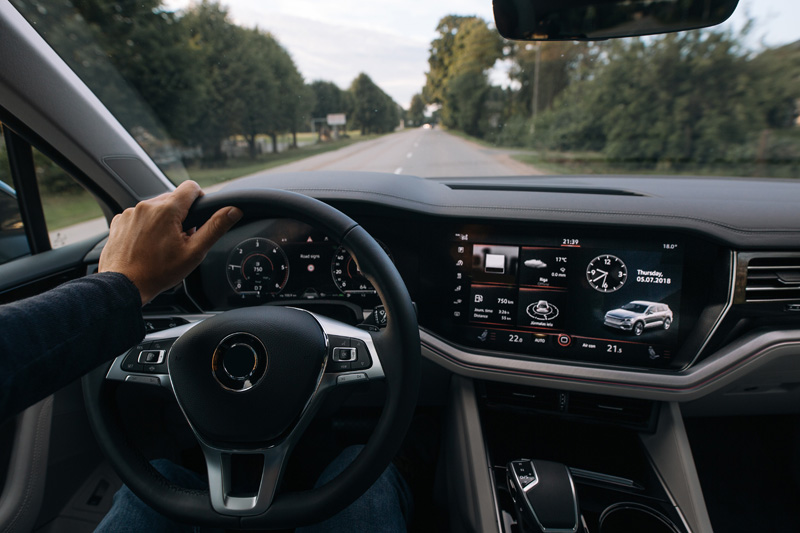
Figure 1. Automobile instrument cluster and centre console. (Source: Shutterstock / BoJack)
Providing power rails for automobile instrument clusters and radio head units presents many conflicting design challenges. These include finding a highly efficient switching regulator with low quiescent current (IQ) that can generate a low output voltage directly from the vehicle battery, while still maintaining low EMI.
Introduction
Even as the fuel efficiency of modern automobiles increases, they are burdened with ever-increasing electrical demands. These include the numerous in-cabin convenience, telematics connectivity and infotainment features that provide information to the driver via the vehicle instrument cluster and/or heads-up display (Figure 1) and are controlled using touchscreens and switches located on the center console (commonly referred to as the radio head unit).
In this article, we review the challenge of providing multiple supply rails to these systems using the vehicle battery as voltage input. We discuss the challenges of meeting the required regulator output voltage range while maintaining low quiescent current (IQ) and low EMI. We also show how a new automotive power management IC (PMIC) removes the compromises associated with alternative solutions in meeting these challenges.
Automotive Power Requirements
To limit heat dissipation, automotive applications require highly efficient DC-DC converters that meet stringent manufacturer quiescent current requirements. These converters must operate with a low input battery voltage to support cold-crank and start-stop events. A common approach to managing cold crank is to use multiple PMICs (and other components) to step down the battery voltage with two stages of buck regulators. This requires complex circuit design and layout, which increases the solution size. This approach is also more susceptible to EMI interference, making it difficult to meet EMI standards such as CISPR class 5. Another concern arises where loads are suddenly disconnected from the car battery (load-dump event) causing the rail voltage to suddenly spike, which can create potentially destructive transient voltages as high as 40V.
Uncompromising Performance
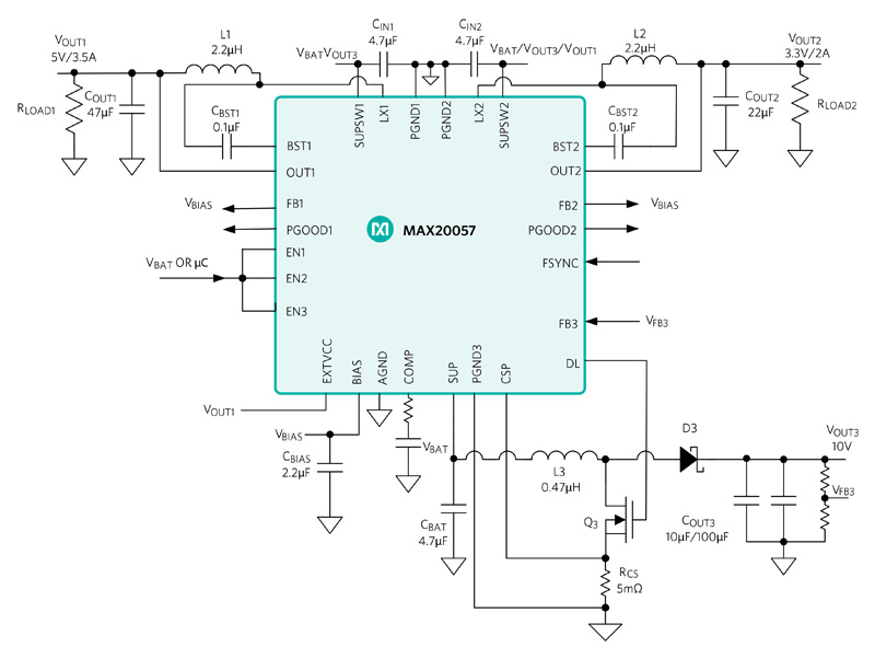
Instead of using a two-stage step-down, a more straightforward approach is to use an integrated PMIC such as the MAX20057shown in Figure 2, which has several advantages over other automotive PMICs.
Click image to enlarge
Figure 2. The MAX20057 36V boost controller with dual 3.5A/2A synchronous buck converters for automotive applications
This highly integrated triple-output PMIC includes two synchronous buck converters (3.5A and 2A) with an asynchronous boost controller that can be used to provide an adjustable voltage (10V typical) to the buck converters and keep them in regulation during cold-crank operation even if the battery voltage falls as low as the 2V battery input. The buck converters have a wide 3.5V to 36V input operating voltage range with exceptionally low operating current requirements of only 10µA (VOUT = 5V) and 8µA (VOUT = 3.3V), making it ideal for voltage regulation when an automobile is switched off for extended periods of time.
EMI Mitigation
To address critical EMI concerns, this PMIC has a user-selectable spread-spectrum function which provides significant reduction in peak EMI levels. This feature spreads spurious energy across a wider frequency band while also lowering its magnitude. Regulator switching frequency is fixed at either 400kHz or 2.1MHz. High switching frequency provides multiple benefits such as requiring smaller external components and reducing output voltage ripple while also guaranteeing no AM band interference. This PMIC can be programmed to operate in any one of three modes for optimized performance as required, i.e., forced fixed-frequency operation, skip mode with ultra-low quiescent current, and phase-locked synchronization to an external clock.
Higher Voltage Conversion Ratio
While some automotive PMICs include buck regulators that provide low output voltages from a relatively wide input range, they do so by running at a low switching frequency. The reason for this is because the minimum voltage conversion ratio (VOUT/VIN) is limited by the regulator’s minimum controllable “on-time” (typically 60ns to 120ns). For proper fixed-frequency pulse-width modulation (PWM) operation and optimal efficiency, buck regulators must operate in continuous conduction mode (CCM) during normal operating conditions. In CCM, the minimum output to input voltage ratio is determined by the following formula:
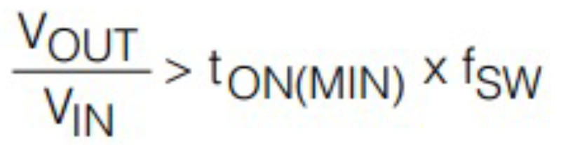
This means that for a typical buck regulator with a minimum “on-time” of 120ns and a 12V input, maintaining CCM at 2.1MHz means the output voltage can go no lower than 3V (realistically, allowing for design margin this could be up to 5V in some circumstances). Achieving lower output voltages requirespulse skipping (decreasing the effective duty cycle) but this has the effect of increasing unwanted EMI. In order to maintain a constant switching rate, the switching frequency must be reduced, but this also negatively impacts EMI performance.
This PMIC has a major advantage over other automotive regulators in this regard. With a typical minimum “on-time” of only 20ns, its integrated buck regulators can theoretically achieve an output voltage as low 0.5V (for 12V battery input with 2.1MHz switching frequency). This figure is below the minimum specified regulated output voltage (1V), meaning it can be used to supply low voltage rails without the need to reduce switching frequency. This allows it to maintain excellent EMI performance at low output voltage levels.
Other variants of this PMIC include the MAX20457, which has dual 3.5/2.5A buck converters (no boost controller) and the MAX20458, which has a single 3.5A buck converter and boost controller. All versions are pin-compatible (meaning a single board design can be used in different applications) and they are specified for the automotive -40°C to +125°C operating temperature range.
Summary
In this article, we reviewed the requirements for providing power to the infotainment, telematics, and head unit systems located within the instrument cluster and center console of an automobile. We explained why some solutions trade off output voltage range for EMI performance and showed how a highly efficient, low ‘on-time’, automotive PMIC is designed to overcome this compromise. This makes it highly suitable for use in all types of vehicles, including those using stop-start technology.