Digital power techniques set new standards for flexibility
Since the origin of mobile communication, various techniques based on software and hardware have been implemented to optimize energy efficiency. In every telecommunication system there are DC/DC converters and point-of-load conversion systems. The latest generation of power-modules embeds digital cores with communication interfaces to add a new functional dimension - flexibility. Following a gestation period of several decades, digital power control techniques are rapidly gaining market share as designers increasingly appreciate the advantages that the technology offers over its analog counterpart. Despite even more uncertain economic times than those of today, estimates made by power industry analysts in August 2009 awarded digital power an approximately 20% compound annual growth rate for the next five years, and the likelihood is that this figure was somewhat pessimisticâ�"the same analysts thought 45% more appropriate just twelve months previously. Forecast accuracy apart, the key to any technology achieving rapid acceptance and sustainable growth lies with delivering tangible benefits at competitive cost.
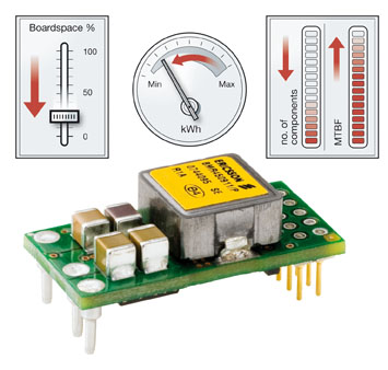
As many designers have discovered, the combination of digital power control and digital power management exceeds routine evolutionary expectations to represent a real, cost-effective step change in overall capability. Here, digital power control refers to implementing the inner control loop of a power converter with digital circuitry rather than using familiar analog schemes. For a simple buck converter, this means substituting an analog-to-digital converter for the traditional error-signal feedback amplifier, and deriving correction for the pulse-width modulator that drives the power switches using digital signal processing techniques in place of a voltage reference, ramp generator, and comparator. By contrast, digital power management denotes supervisory and control circuitry that communicates via a digital I/O scheme, which today almost invariably exploits the PMBusâ„¢ interface that has become the power-industry standard. A converter that combines both of these digital power concepts can actively manage its conversion process to optimize efficiency for changing line and load conditions while including all of the power management system within the same package. Digital configurability delivers life-cycle benefits But digital power has much more to offer than bettering the electrical performance and power-density requirements that previously dominated the mindset of power supply designers. Essentially, such performance improvements are due to the ability of a digital control loop to adapt its dynamics to optimally suit line and load conditions in real time; by contrast, passive components set an analog converter's responses, which are inevitably a compromise between stability and dynamic response for the expected operating conditions. But in developing its 3E concept that embraces enhanced performance, energy management, and end-user value, Ericsson recognized that digital power could offer benefits that apply throughout a product's lifecycle. As the digital converter's core is a mixed-signal IC it's possible to pack the supervisory measurement and control hardware together with its PMBus interface onto the same slice of silicon at negligible additional cost. This approach optimizes the electrical coupling between the converter's core and its control system, minimizes power consumption, and slashes the amount of PCB real estate that's necessary to accommodate equivalent functionality using analog-based solutions. Crucially, it's now possible to configure the digital converter when it is initially made, during the development phase of the power-system designer's application, at the distributor's depot, when the equipment is manufactured, and/or when it is operating within the end-user's equipment. This unparalleled degree of flexibility extends the programmable logic model to the power conversion industry for the first time. Each 3E family power converter offers an array of programmable parameters that includes output voltage selection, turn-on/off delay times to implement power sequencing for multi-rail loads, slew rate control that provides inrush current protection, voltage margining for system testing, and multiple thresholds for warning and fault conditions for overcurrent, overtemperature, and under- and overvoltage. It's even possible to adjust the response of a digital converter's control loop to optimize its performance for a particular set of load and bulk output capacitance conditions.
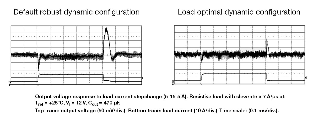
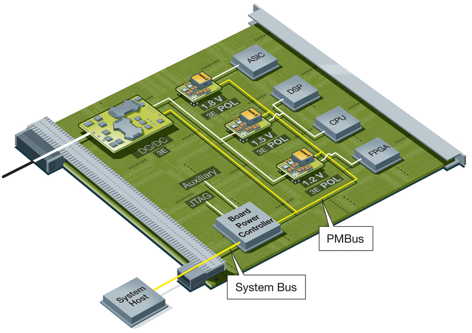
Figure 2 shows the result of fine-tuning the constants that set the responses of a 3E point-of-load regulator's control loop to optimize its transient response for a given environment. This is the digital equivalent of moving the poles-and-zeroes in an analog converter by continuously adjusting the values of resistors and capacitors within its feedback loop, which is practically inconceivable. PMBusâ„¢ is a key enabler The PMBus can be invaluable during product evaluation and development. Here, the board power manager that controls PMBus-compatible devices might be a PC connected to a prototype board via a suitable adapter. Because the physical layer of PMBus relies upon SMBusâ�"which is a development of I2Câ�"PMBus is generally limited to the board domain, leaving designers free to implement their choice of backplane connectivity. Figure 3 shows the general scheme.
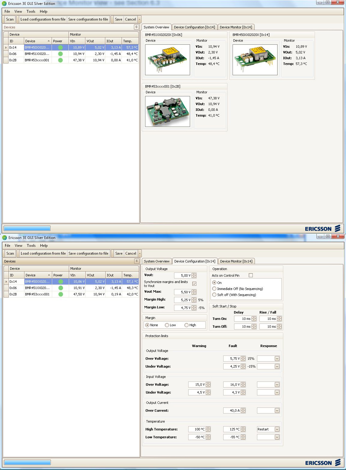
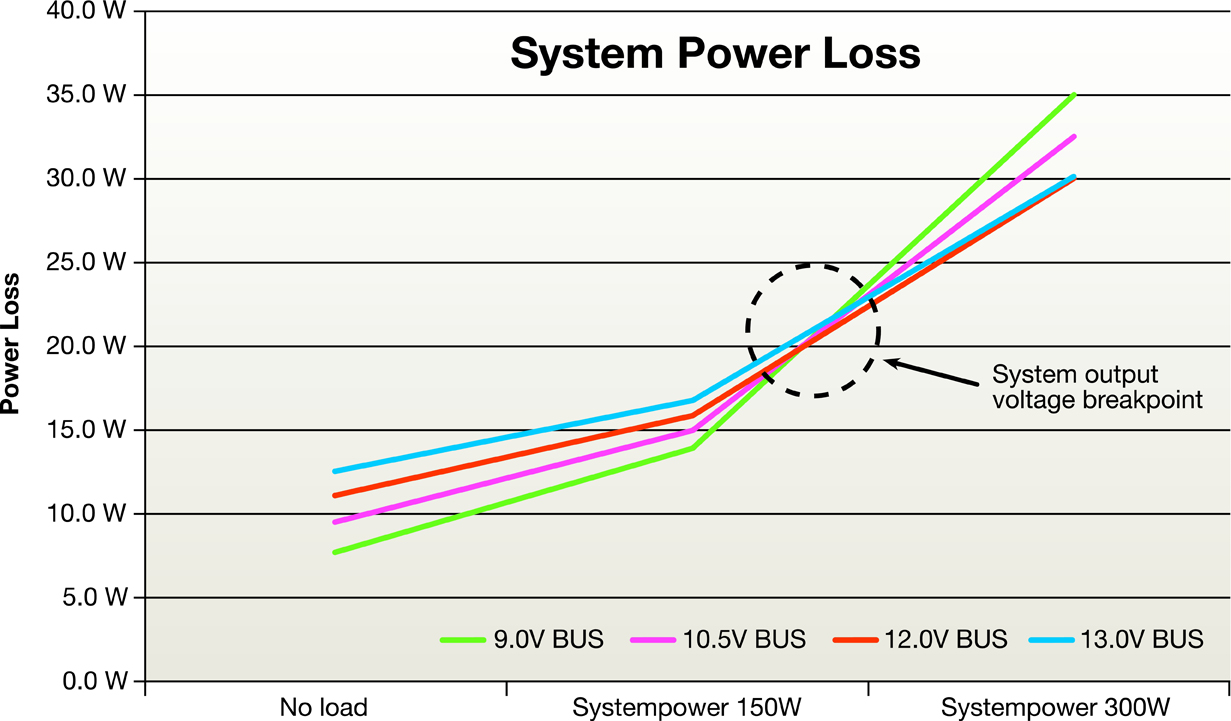
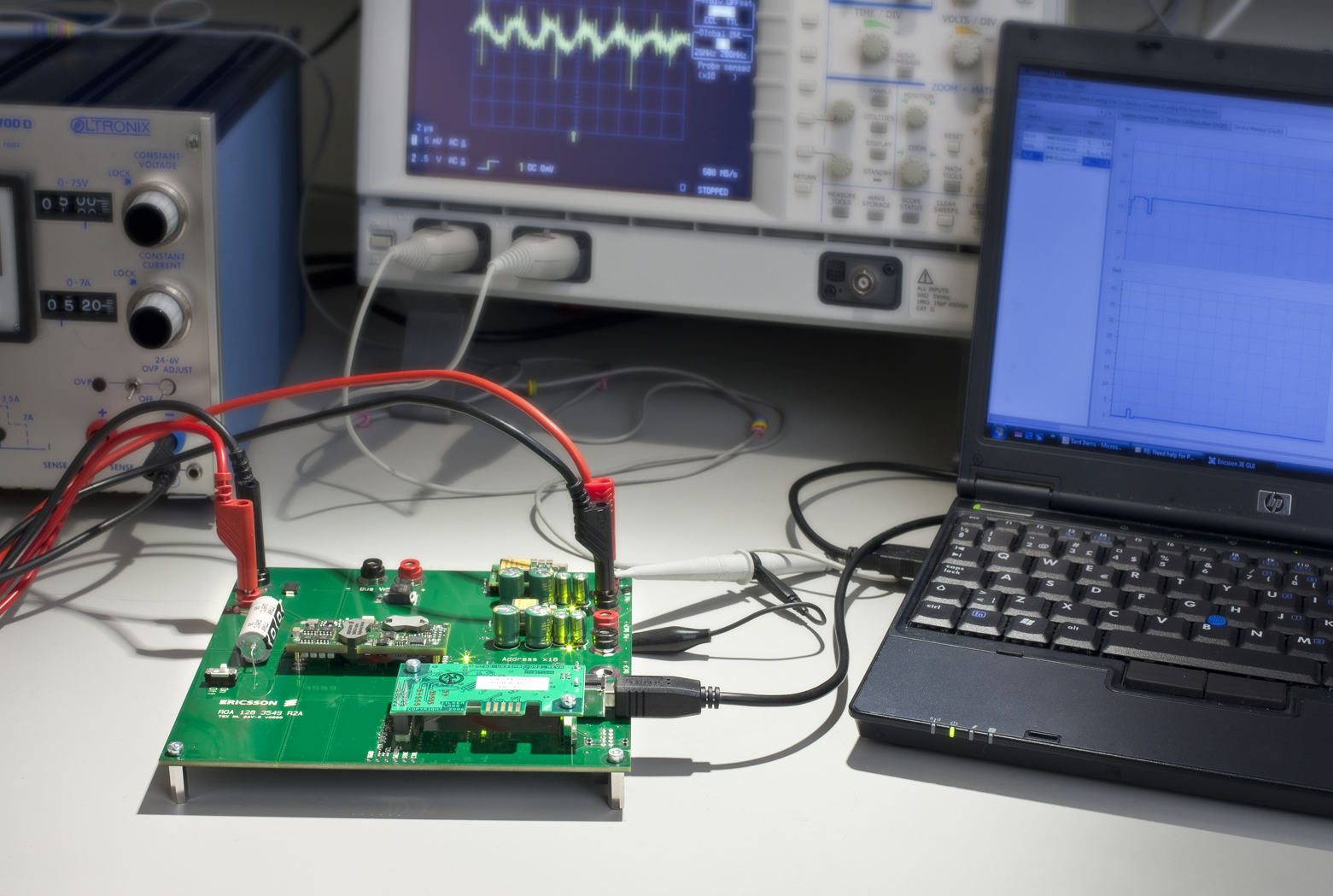
To make development immediately available, Ericsson developed a PC-compatible evaluation kit for 3E products that includes a USB-to-PMBus adapter and driver software that substitute for the board power manager. The PC and the kit's application software then assume the role of system host and user interface. This approach provides an extremely fast method for experimenting with parameters such as output voltage settings, power sequencing routines, voltage margining, and fault handling without any need for hardware changes on the board-under-test. When the designer is satisfied with a set-up, the application software can save a configuration file for each 3E device for later use. While customers can request specific configurations, Ericsson most often delivers 3E parts pre-programmed with a default configuration that reflects a converter's typical application profile. For instance, users can order a point-of-load regulator such as the 20A-rated BMR450 preset to output 1.0, 3.3, 5.0, or 5.5VDC. It is subsequently possible to reprogram the device to any level from 0.6 to 5.5VDC with 1mV resolution via the PMBus (it's also possible to set the product's output voltage from 0.7 to 5.0VDC in 25 steps with a resistor). As a result, one device covers a range of output voltages, permitting inventory reductions and easing logistics management. It's also worth noting that the BMR450 and its 40A companion BMR451 can share a common PCB layout, allowing designers to exchange converters as a system's power needs evolve. Similar benefits apply to all 3E family power converters. If a one-time change of output voltage or any other programmable parameter is all that's necessary, a logical time to do this is at the ATE phase of board manufacture. Alternatively, a distributor may offer a programming service. Assuming a simple end-user application such as upgrading an analog design, it's possible to dispense with board power management logic on the target board. However, including full PMBus connectivity vastly improves the range of options that are available to power-system designers. As the PMBus requires just four conductors and a low-cost microcontroller easily accommodates the board power management logic, this approach is well worth considering. Implementing PMBus connectivity allows the system host to monitor each PMBus-compatible device throughout the equipment's lifetime. Depending upon the sophistication of the system's supervisory software, this data-gathering ability might form the basis for energy cost analysis, root-cause failure analysis, or satisfy other user-specific functions. It may also help avoid system failures. For instance, if the supervisory software detects an unusually high pattern of warning conditions for a particular device, it may signal a service alert to swap out the suspect device before it fails. Similarly, if a power converter's output voltage drifts slightly over time or as a result of wide temperature variations, supervisory software could adjust the device back into full specification. Another possibility that monitoring a board's power consumption offers is dynamic energy conservation, where supervisory software intelligently varies the output voltage that the intermediate bus converter supplies to the point-of-load regulators. Because virtually all power converters are least efficient at low loads, reprogramming the advanced bus converter from say 12VDC down to 9VDC saves power dissipation while the point-of-load regulators are running under light load.
When more power is required, supervisory software can seamlessly ramp up the intermediate bus voltage to its optimal level for the new load conditions. Where a pair of power converters operate in a parallel current-sharing arrangement, it will save energy to turn off one if the load level falls within the capability of a single converter. This active approach to power management particularly suits systems that spend significant periods under widely different load conditions. This is just the beginning It's important to emphasize that these example scenarios represent just a few of the possibilities 3E power converters with PMBus connectivity make possible, and innovative designers will doubtless find new ones. Also, any of these converters can upgrade analog designs with no special effort on the designer's behalf. They can easily operate stand-alone as they offer analog-style functions such as output voltage adjustment via a single resistor, remote voltage sensing, and single-pin hardware on/off control. The "set-and-forget" capability that PMBus mandates also means that any 3E power converter can be pre-programmed with user-defined parameters that the device then retains for its lifetime or until re-programmed. This makes it possible to fine-tune a converter for a particular application without requiring PMBus in the target system.
Compared with well-known analog techniques, the downside of digital power conversion is the very substantial amount of R&D effort that's necessary to produce a production-worthy digital converterâ�"which is a prime reason for selecting proven, pre-qualified solutions. To help ease users into the digital power environment, Ericsson offers application engineering assistance and complements its evaluation kit with a large archive of technical papers and application information. www.ericsson.com/powermodules