Powering IoT Modules w/ Supercapacitors, Solar Panels, and Power Management ICs

The IoT module market is growing at a rapid rate due to their low cost, ease of implementation, and well documented positive impact on end-user efficiency, reliability, and total system cost
Figure 1: A schematic view of Analog Devices’ LTC31102A, bidirectional, buck-boost DC/DC regulator and charger/balancer
To further improve IoT modules, many manufacturers are developing set-and-forget IoT modules designed to either eliminate batteries or extend battery life so significantly that end-users rarely to never have to concern themselves with powering their IoT modules.
In pursuit of this goal, IoT module manufacturers are working to drastically reduce the amount of power these devices consume and employing novel IC chipsets that leverage supercapacitors to provide quality power from harvested or scavenged energy sources, such as solar panels or cellular, Wi-Fi, and radio transmitters, which tend to emit enough ambient electromagnetic energy to power low-energy electronics.
Here, we’ll address the efficacy and performance of supercapacitors as power sources for set-and-forget IoT modules when used in combination with solar panels and power management ICs (PMICs) that provide bidirectional buck-boost DC/DC regulation, supercapacitor cell charging and balancing functions, and automatic power switching to supercapacitors as primary power is lost.
IC Device Technology
IC device progress is largely defined by higher gate densities and faster processing speeds. However, while faster CPUs, more powerful FPGAs, and larger memory chips are of immense value and importance, the significant progress that’s been made in PMICs is equally advantageous and remarkably under-recognized.
The LTC3110 by Analog Devices is an excellent example of a small, easy-to-use, practical, and efficient PMIC. This 2A, bidirectional buck-boost DC/DC regulator and charger/balance has a wide operating voltage range spanning 1.8V to 5.5V and a selectable output/backup voltage range of 1.8V to 5.25V, is available in thermally enhanced TSSOP-24 and 4×4mm QFN-24 packages, and provides ~93% power conversion efficiency.
When power is present, the device provides power to the load in addition to balancing and charging a supercapacitor stack. When power is lost, the PMIC automatically switches from drawing on input power to drawing power from the charged supercapacitors — either at, above, or below the supercapacitor charge level — to provide design engineers with maximum flexibility for powering the end load.
As such, the LTC3110 is well suited for providing power to set-and-forget IoT modules and other RF systems with battery or capacitor backups. One such configuration could be managing power from a solar panel, balancing and charging multiple supercapacitors, and automatically switching to the supercapacitor power source when the solar panel is unable to provide power for the load.
Supercapacitor Technology
The other critical component in set-and-forget IoT module designs is the supercapacitor. Supercapacitors, or electrochemical double-layer capacitors (EDLCs), have experienced significant technological advances in recent years and, through rigorous performance testing, have earned recognition as effective solutions for storing energy in a wide variety of applications.
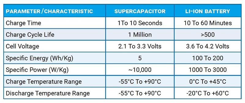
Supercapacitors are a compromise between traditional dielectric capacitors and batteries, as evidenced by Figure 2. Supercapacitors provide high capacitance per unit volume and — even more importantly — the ability to charge and discharge at exceptionally high rates of speed. In fact, supercapacitors’ very high levels of current charge and discharge is one of their most celebrated features, as that’s what enables their massive specific power capabilities. Another acclaimed feature of supercapacitors is their ability to achieve an especially high number of charge/discharge cycles. In both lab tests and case studies, supercapacitors have proven capable of up to one million cycles under recommended use conditions.
Click image to enlarge
Figure 2: The performance characteristics of supercapacitors compared to those of lithium-ion batteries
Some studies have even suggested that supercapacitors are poised to eventually replace batteries, which could enable advantages including greater safety, faster charging, and smaller device sizes and significantly reduce the need for complex and costly battery management systems.5 However, the extent to which these hypothetical advantages prove true depends on the charging source and the circuit load. IoT modules, for instance, are typically rated for less than 5V, with 2.5V designs accounting for quite a large percentage, and their current loads are typically small and pulsed in nature.
From a materials point of view, a wide range of developments with the potential to expand supercapacitors’ already-high available capacitance range by an order of magnitude or more are clearly visible on the horizon. However, the test data addressed herein exclusively pertains to acetonitrile-chemistry (ACN-chemistry) devices and assumes that the operating conditions required for end-use equipment are within the standard range of supercapacitor operating temperatures, which extends from -40°C to +85°C.
Supercapacitor Form Factors
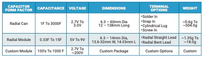
Supercapacitors are also available in multiple form factors, which further contributes to their ease of implementation in end systems. The three most common supercapacitor form factors are radial can, radial module, and custom module designs.
Click image to enlarge
Figure 3: The three most common supercapacitor form factors and their typical physical and performance characteristics
Radial Can Form Factors: Supercapacitors with radial can form factors were chosen for our “Powering IoT Modules” study because they offer multiple product series, multiple voltage ratings, 10 different case sizes, and the greatest selection in terms of capacitance values and, as such, deliver maximum design flexibility.
Radial can supercapacitors are commonly used alone in lower voltage designs, but multiple-can configurations be used to obtain the proper voltage and energy ratings for higher voltage loads and can be balanced using active or passive methods.
Supercapacitor balancing helps ensure long lifetimes for multiple supercapacitors used in series, as balancing each supercapacitor prevents them from damaging the other supercapacitors in the stack with over-voltage energy. Passive supercapacitor balancing has the advantage of being the cheapest, smallest, and easiest to use since it's accomplished with a resistor. The biggest disadvantage is that passive balancing reduces efficiency since power is dissipated in the balancing resistor. Active semiconductor balancing is the most efficient and exacting, but it’s also the most expensive. In addition, the size required for active balance solutions varies greatly based on the number of cells that need balancing, as well as the size of the cells and/or semiconductors used for balancing.
Radial Module Form Factors: Supercapacitors with radial module form factors are typically manufactured in series comprised of two to three radial can supercapacitors packaged as single modules. These form factors offer maximum efficiency in terms of package density, as well as higher voltage ratings, which can be especially beneficial for simplifying higher voltage battery-powered application designs. Radial modules can be balanced or unbalanced and are often available in both hard-shell and heat-shrink packaging designed for use in enhanced and standard reliability designs.
Custom Module Form Factors: Supercapacitors with custom module form factors are also made using combinations of radial can supercapacitors, but they typically require both charge control and cell balancing. Custom modules can have massive energy ratings and, as such, can be made to replace batteries in a wide variety of applications including LED-based lighting, wirelessly charged equipment and devices, and even pallet trucks, forklifts, and industrial robots.
Supercapacitor Reliability
Since supercapacitor reliability is a function of applied voltage and temperature, as evidenced by previous work conducted by DeRose et al., supercapacitors need to be properly derated to achieve reliable, long-term operation regardless of the specific package configuration.2,3 In this work, a variety of ACN-chemistry supercapacitors were subjected to a matrix test in which voltage, temperature, and humidity stress levels were varied while the capacitance and equivalent series resistance (ESR) of the devices under test were measured to determine stress effects.
The resulting test data was used to develop a series of graphs that illustrate mean time to failure (MTTF) in years at various applied voltages and temperatures. These graphs indicate that expected supercapacitor lifespans more than double for every 10°C reduction in operating temperature and double again for every 0.1V reduction in operating voltage, as shown in Figure 4.

Click image to enlarge
Figure 4: This graph illustrates the impact of voltage derating on ACN-chemistry supercapacitors rated for 5.4V and 5.0V, as well as their MTTF in years at various voltages and temperatures
Supercapacitor Sizing
When it comes to sizing supercapacitors for battery hold-up or replacement, the BOM cost and PCB volume tend to be dominated by the supercapacitors, as noted by Analog Devices’ Holtkamp and Alonso.4 So, the key to an efficient design is to provide for the peak power needs without excessive conservatism, since that results in increased part cost and PCB volume.
To meet the power hold-up requirements of any project, the energy of the stack must be greater than the energy of the load. The extent to which designers should be conservative is impacted by the supercapacitor's temperature and the quality of the charge voltage, since both directly affect cell reliability.
In our test circuit, the LTC3110 provides a balanced, well-regulated voltage on the cell to ensure that the reliability of the supercapacitor storage bank isn’t negatively impacted by charging voltage stability. Whenever charging sources exhibit wildly swinging voltages, the cell stack needs to be derated by a higher series stack voltage, which can be achieved by putting more supercapacitors in series, or some form of added voltage regulation.
Once design engineers have appropriately derated the supercapacitor(s) for temperature and voltage, there are three cell sizing factors to consider: the aging effects of the supercapacitor, the converter efficiency, and the PMIC dropout voltage.
Aging Effects of the Supercapacitor: Generally, when a supercapacitor reaches the end of its lifespan, its capacitance drops to 70% of the specified value and its ESR rises to 200% of the specified ESR. So, capacitor aging must be taken into account in order to ensure that stored energy values remain greater than the system’s energy needs.
Converter Efficiency: The converter efficiency is a direct function of the PMIC chosen.
PMIC Dropout Voltage: The dropout voltage is the point at which the supercapacitor's voltage is too low to power the PMIC and, as such, is PMIC-dependent.
The tests conducted in this study didn’t concentrate on any specific cell sizing since tests were conducted at 25°C using supercapacitors with well-balanced and stable voltages. These tests were also conducted on a short-term basis, so aging effects weren’t a factor. In addition, the converter efficiency and dropout voltages were all the same in comparisons since the LTC3110 was used for all test cases.
Test Board Description
The purpose of our “Powering IoT Modules” study was to demonstrate the efficacy and performance of supercapacitors as power sources for set-and-forget IoT modules when used in combination with solar panels and PMICs that provide bidirectional buck-boost DC/DC regulation, supercapacitor cell charging and balancing functions, and automatic power switching to supercapacitors as primary power is lost.
All testing was conducted on an Analog Devices DC1964A demo board that was based on its LTC3110 PMIC and equipped with two AVX SCC Series radial can supercapacitors rated for 2.7V and either 1F or 7F capacitance and subjected to two current loads, 50mA and 100mA, at a 10% duty cycle (1ms on and 9ms off).1 The capacitor values, current load, and duty cycle test cases allow engineers to extrapolate power supplied for other known loads and duty cycles while limiting the test duration to record data.

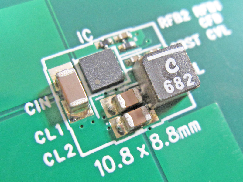
Click image to enlarge
Figure 5: An Analog Devices DC1964A demo board based on its LTC3110 PMIC and equipped with two AVX SCC Series supercapacitors rated for 2.7V
When the system rail is powered, the LTC3110 powers the load as well as charges and balances the two supercapacitors for backup energy storage. When the input power is eliminated, the LTC3110 automatically begins drawing stored energy from the supercapacitors to power the downstream load and continues doing so until its dropout voltage is reached or input power is restored.
Test Setup
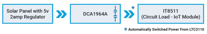
Our test configuration (see Figure 6) used a low-cost, industrial solar panel to drive a 5V, 2A regulator that provided input power to the DC1964A evaluation board. An ITECH IT8511 DC electronic load was placed on the DC1964A evaluation board and test data was recorded for 50mA and 100mA loads at a 10% duty cycle (1ms on and 9ms off).
Click image to enlarge
Figure 6: The test configuration employed in our “Powering IoT Modules” study
It’s also important to note that, although the supercapacitors chosen in the test matrix were rated for 1F and 7F, they were placed in a series stack to double their voltage and, in that configuration, their capacitance dropped to 0.5F and 3.5F.
In addition, although the DC1964A evaluation board offers various configurations, we used the simplest of its configurations to illustrate the ease of creating a set-and-forget power source based on solar harvesting and supercapacitor storage. The IT8511 was configured to represent the power consumed by an IoT module and data was recorded in real-time after the capacitor stack had been charged by the solar panel and the input power source was removed from the DC1964A board.
Test Results
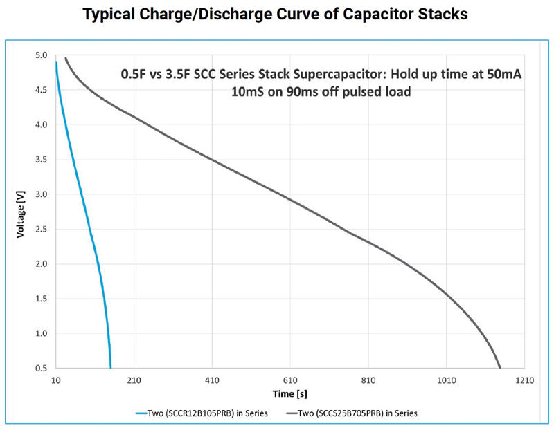
The load currents, duty cycles, and capacitance values we tested were driven by survey data collected from IoT designers and designed to approximate their needs. The following graphs compare the charge and discharge characteristics of the 0.5F and 3.5F stacks when under test at 25°C and 50mA and 100mA loads (Figures 7a and 7b). The supercapacitors were charged and recharged using the input power the solar panel fed into the DC1964A. Once that power source was removed, the PMIC instead routed power from the supercapacitors to the load. The voltage of the supercapacitor stack was monitored during this discharge state and plotted against time to reveal the measure of usable output voltage from the IC based on the supercapacitor charge state.
Click image to enlarge
Figure 7a: This graph illustrates 0.5F vs 3.5F supercapacitor stacks with a 50mA load and a 10% duty cycle

Click image to enlarge
Figure 7b: This graph illustrates 0.5F vs 3.5F supercapacitor stacks with a 100mA load and a 10% duty cycle
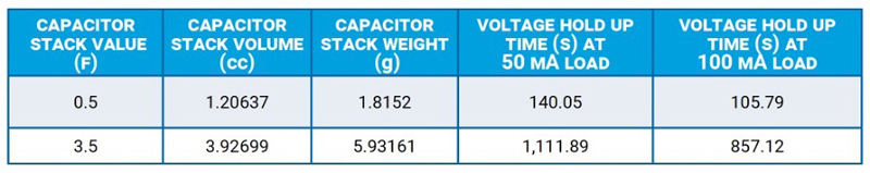
In all test cases, the AVX supercapacitors were the only source of output power on the evaluation board. Although the test could have been performed hundreds of thousands of times, testing was limited to fewer than 10 charge/discharge cycles due to both time limitations and the fact that supercapacitors can be charged and discharged many hundreds of thousands of times without measurable wear-out. Figure 8 compares the capacitor stack value, volume, weight, and power hold-up time in seconds under 50mA and 100 mA loads at a 10% duty cycle.
Click image to enlarge
Figure 8: This table compares the supercapacitor stack properties and hold-up times under 50ma and 100ma loads at a 10% duty cycle
Conclusion
The concept of set-and-forget IoT modules is very attractive to IoT end-users, and recent advancements in both power management semiconductor (PMIC) and supercapacitor technologies have resulted in the development of multiple series of small, high-efficiency ICs ideal for use in long-life power source scenarios, which has made their market introduction a real near-term possibility.
Supercapacitors compare favorably to Li-ion batteries in terms of charge/discharge speed, the number of charges they’re capable of, their operating temperature range, and their specific power, but their energy density is just one-tenth that of Li-ion batteries. However, even with that disadvantage, supercapacitors can still provide highly reliable energy storage that can be called upon when primary power sources are eliminated for a portion of existing loads.
Although our “Powering IoT Modules” study surely didn’t directly address all of the power requirements for the full range of IoT modules available, the study did provide a sound example of how simple and effective it is to implement solar panels, supercapacitors, and PMICs with bidirectional buck-boost DC/DC regulation, supercapacitor cell charging and balancing functions, and automatic power switching to supercapacitors as primary power is lost. As such, we hope it encourages end-users to strongly consider a combination of energy harvesting and supercapacitors as a power source for set-and-forget IoT modules.