Author:
Carlos Castro, Global Director Automotive Power Control, Semiconductor Business Unit, Littelfuse
Date
07/22/2019
 PDF
PDF
Click image to enlarge
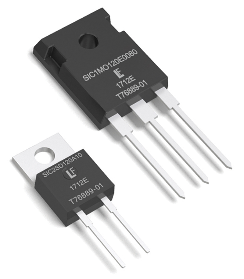
Figure 1. SiC Schottky diodes and MOSFETs, like these pictured from Littelfuse, lower power switching losses compared to Si devices.
Electric vehicles are poised for meteoric growth, rising from an estimated 6 million vehicles in 2019 to 16 million vehicles in 2023. New technologies are enabling this dramatic change, including more efficient power conversion and higher power density. New circuit protection strategies are also required to protect the battery management system (BMS) from higher power.
Efficient Power Conversion
Power losses reduce a vehicle’s driving range. Also, during vehicle charging, losses cause engineering challenges in the form of heat and charging time. This is why the industry is adopting wide band gap power semiconductor devices that provide higher power efficiency during power conversion. In particular, SiC devices are now affordable and have automotive-level reliability (Figure 1).
Another advantage of SiC devices is that they leverage smaller passive components (i.e. inductors) and less need for heat sinks. In hybrid vehicles especially, space is at a premium, and even a small amount of weight has a cost in vehicle performance.
Power Density
As the power density of lithium-ion batteries increases, vehicles are achieving longer driving ranges per charge, making EVs more attractive to consumers. In parallel, high-power vehicle charging stations are emerging that dramatically shorten charging times, which will also increase adoption of electric vehicles.
Major automobile companies are offering cars with lithium batteries capable of 250-Watt hours per kilogram (Wh/kg), with targets to reach 350 Wh/kg in a few years. Government and industry researchers are working on battery designs that may far eclipse the power density that is available today.
Lithium-ion batteries offer vehicle designers a long charging cycle life and power density, however they can be finicky. Overcharging and high discharging reduces the lifespan and efficiency of lithium-ion batteries. Extreme current flows may lead to shorts and dendritic lithium plating that eventually destroys the cell. Undervoltage can break down electrodes. Extreme battery temperature can cause electrical shorts and the outgassing of flammable gas. For the batteries to operate safely, the BMS must carefully manage charging and discharging and maintain a state of charge of roughly 20-to-90%.
Circuit Protection
As battery power density increases, and as charging voltage increases, so does importance of proper circuit protection of batteries and the BMS, which lies at the heart of this green revolution. If it is not adequately protected against a variety of electrical threats, then battery failures will turn off consumers and, in the worst case, lead to dangerous fires and shock hazards.
The challenge for vehicle designers is that standards have yet to emerge for the BMS. Unlike the mature technology of combustion engines, electrified vehicles are still early in their development. Each vehicle manufacture is attempting to find the best way by doing it a new way: new architectures, new voltage classes, and new ways to adapt performance from mechanical to electric metrics. This has led to confusion about how to best protect the circuits.
Overcurrent protection
The BMS and batteries face a variety of electrical threats. Given that it is a high-energy system operating at hundreds of amps, the most obvious threat is overcurrent. In the case of an accident, a punctured or crumpled battery can cause a fire or shock hazard by making contact with the metal chassis of the car.
For this reason, DC fuses are deployed at multiple strategic locations. They quickly interrupt high-value overcurrent and short circuits. The fuses used in electric vehicle applications must be automotive qualified. It’s not easy. Unlike the fuses used to protect lithium batteries in tablets and mobile phones, automotive fuses must withstand extreme shock and vibration. An automotive fuse is expected to remain reliable over a fifteen-year life cycle including 8,000 hours of operation and 150,000 miles of road vibrations.A small form factor is essential to reduce mass that can be affected by vibration, however the high power involved with electric vehicles requires the fuse to be relatively large. Temperature is a compounding environmental factor; the fuses must have a low-temperature derating so they don’t open prematurely at elevated temperatures.
Surge and ESD protection
The BMS communicates continuously with the charging system to prevent cells from being overcharged. It controls the charging rate, slowing it as the battery gets close to reaching capacity in order to avoid overheating. The BMS controls the charging rate according to the capacity of the battery pack, with an increasing number of vehicles having high-capacity batteries capable of fast charging.
As EV charging moves to higher voltages and currents, the communication between the battery, BMS, and charger is increasingly important and must be protected.
TVS diodes and diode arrays are used to defend communication lines, normally CAN bus, against transient voltages induced by ESD and nearby lightning strikes. The selection of these devices, and their locations in the circuit, depend on the BMS architecture.
BMS architecture
In an electric vehicle, battery cells connect in series, making up a module. As modules connect in series, the total voltage of the system increases. Next, the modules are connected in parallel to increase the energy capacity. As designers add modules to a BMS, cost and complexity increases.
Each module of batteries has cell monitoring systems. These subsystems monitor the voltage for proper balance. Microcontrollers then oversee each of these modules to provide the highest energy efficiency and longest-life of a battery.
The particular architecture for the BMS determines the protection specifications, such as the interrupt rating and voltage ranges.
In a decentralized architecture, sense balancing IC connect by long wires between the cells and the slave boards. High voltage fuses are used to reduce the risk of a short circuit under high voltage conditions both in the module and between the cells in an accident. If a component is damaged in this decentralized architecture, it can be replaced separately, making it a less expensive and simpler option.
In centralized architecture, all the components integrate into single modules. However, if one component fails, the entire module must be replaced, at a higher cost.
Under this architecture, the distance is smaller between the cells and slave boards, making an accident less likely to cause short circuit under high voltage conditions. Nevertheless, lower-cost low- and medium-voltage fuses should be used to protect against component failure and contamination on the BMS board. Two types of failure must be taken into account, short circuits and overload conditions.
Because of the sensing lines at each cell, there is the potential for a short circuit in any cell. The cell monitor block or direct line must also be fused to avoid overcurrent damage.
Applying circuit protection
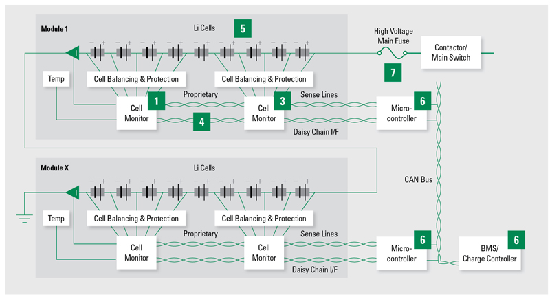
Figure 2 shows the system elements at risk of damage and the type of device best suited for their circuit protection.
· ICs used to monitor cells – TVS diodes protect against overvoltage
· Communication lines between units – TVS diode arrays guard against EDS
· Battery ICs – high voltage TVS diodes in case of voltage transients
· Microcontrollers – TVS diode arrays
· Main switch – high-voltage-high current fuse in series with the main switch to act as a final protection barrier
· Inverters and DC/DC converters – high-voltage TVS diodes
Click image to enlarge
Figure 2. A BMS block diagram. Locations for circuit protection include fuses (1), TVS diodes (3, 5), TVS diode arrays (4, 6), and high voltage fuse (7)
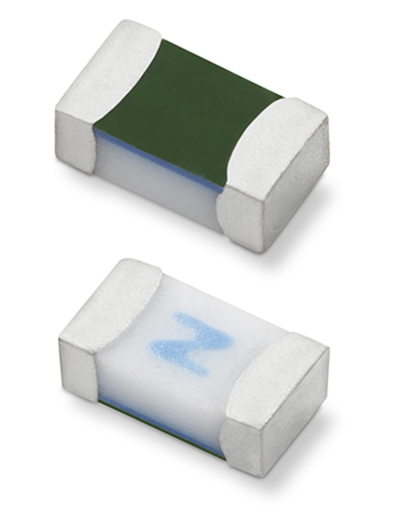
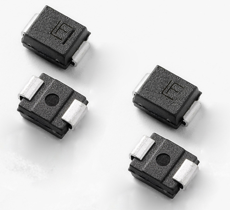
Automotive-grade circuit-protection components are available from a number of suppliers (Figure 3a & 3b). Because of the mission-critical nature of automotive circuit protection, design engineers will benefit from working with suppliers who understand the entire BMS ecosystem and offer a variety of technology solutions.
Click image to enlarge
Figure 3a & Figure 3b: BMS protection requires AEC-Q automotive qualified components. Examples include the 441A Ceramic Fuse and the TPSMB TVS Diode from Littelfuse. TVS diodes guard against secondary induced transient voltages
Unlike many applications in which circuit protection is almost an afterthought, vehicle electrification is one area in which design engineers recognize its critical role. Testing is moving from the final phase to a step early in the process. Many suppliers offer customized simulation testing that can validate designs during development. Standard tests don’t exist in this quickly evolving market, so designers and component suppliers must work as a team and develop expertise together. What’s more, to reach optimal protection selection within automotive safety standards, automotive engineers should be educated in current safety standards and their requirements. Often their suppliers are in the best position educate them.
As both consumers and governments push automotive manufacturers toward a greener future, they must find solutions to a host of engineering challenges, including circuit protection. Working with knowledgeable suppliers, they are creating a new generation of safe and reliable electric vehicles.
Littelfuse, Inc.