Using multiphase current-mode controllers can improve performance
The sub-28 nanometer Field Programmable Gate Arrays (FPGAs) now available feature the in-dustry’s only hard floating-point digital signal processing (DSP) blocks with speeds up to 1,500 Gbps floating-point operations. Built on sub-28 nm process technology, these FPGAs provide up to 17.4 Gbps for long-reach backplane support and with data rates up to 28.3 Gbps to bring high-end bandwidth performance into midrange devices.
These new FPGAs require up to 105A to power their cores and use VID (Voltage Identification) 6-bit interface to tightly control its operating voltage in 10mV steps for optimum performance. For such high currents it is critical to minimize power supply conduction losses by making the resistance of the current sense element as low as possible. However, a low resistance current sensing element produces a lower ramp voltage which is not conducive for stable operation when using a current mode controller. Low ramp voltages cause a current-mode-controlled switching power supply to have significant jitter and it may become unstable. Accordingly, a voltage mode controller is routinely used instead, even though it has performance deficiencies and potential reliability concerns.
Nevertheless, a current-mode-controlled switching power supply has several advantages over a voltage mode alternative. These are as follows:
1. Higher reliability with fast, cycle-by-cycle current sensing for output short circuit and overload protection.
2. Simpler feedback loop compensation
3. Accurate current sharing in high current multiphase designs.
4. Faster Transient Response
However, for high current outputs, typically greater than 20A per phase, sub-milliohm DCR fer-rite inductors are required for high efficiency. However, these inductors will not produce enough of a voltage ramp signal for a current mode controller to be stable under all operating condi-tions. And so, a voltage mode solution becomes more attractive. That is, until now.
New solutions available
One example of an advanced solution recently released is the current-mode dual-phase DC/DC step-down controller, LTC3877, which has the ability to sense very low ramp voltages and maintain excellent stability. It operates with true current mode control and can be used with very low DC resistance (DCR) power inductors down to 0.3mΩ, due to its novel sensing scheme that enhances the signal-to-noise ratio of the current sense signal. This sensing scheme dramatically reduces the switching jitter normally associated with low DCR resistance applications and the LTC3877’s adjustable current limit can be configured for very low sense voltages from 10mV to 30mV to minimize power loss. This lower inductor DCR allows the maximum output current to be as high as 30A per phase due to the reduced inductor power loss and the ability to sense a lower ramp voltage. As a result, a 4-phase design is able to support a 120A load.
The LTC3877 also incorporates 6-bit VID control that enables 10mV step resolution of the output voltage, a necessary feature when powering FPGAs and ASICs with very tight input voltage tolerances. Up to 12-Phases can be paralleled and clocked out-of-phase to minimize input and out-put filtering.
The LTC3874 phase extender can also be used for high phase count applications which complements Linear Technology’s low DCR peak current mode controllers and provides all the necessary functions for multiphase slave designs, including accurate phase-to-phase current sharing for steady state and dynamic loads. When outputs are paralleled, the LTC3877 maintains better than ±2.5% current mismatch between phases, making it ideal for very high current requirements up to 300A.
The LTC3877 maintains ±1% output voltage accuracy (including internal resistor divider and differential remote sense amplifier errors) over a –40°C to 125°C operating temperature range. Dual onboard differential amplifiers enable remote output voltage sensing for both outputs. High step-down ratios at high operating frequencies are possible due to its 40ns minimum on-time. The LTC3877 has a selectable fixed operating frequency from 250kHz to 1MHz or it can be synchronized to an external clock.
Its onboard all N-channel gate drivers minimize MOSFET switching losses while its DCR temperature compensation maintains a constant current limit threshold over a broad temperature range. Additional features include adjustable soft-start or tracking, foldback current limit, short-circuit soft recovery, output overvoltage protection and two power good output voltage signals. The LTC3877 is housed in a 44-lead 7mm x 7mm QFN package.
As a result, the LTC3877 and LTC3874 combination can be used to provide power for the Core rail by taking advantage of the 6-bit VID interfaces to reduce the FPGA’s static and dynamic power consumption.
120A current solution with VID
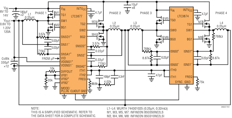
The simplified schematic in Figure 1 shows the LTC3877 being used in conjunction with the LTC3874 dual channel phase extender. The resultant 4-phase design is able to produce up to 120A with the VID controlled output voltage ranging from 0.6V to 1.23V. Each phase is clocked out-of-phase resulting in lower output ripple and faster load step transient response.
Click image to enlarge
Figure 1. The LTC3877/LTC3874 Schematic for low Voltage 120A Output
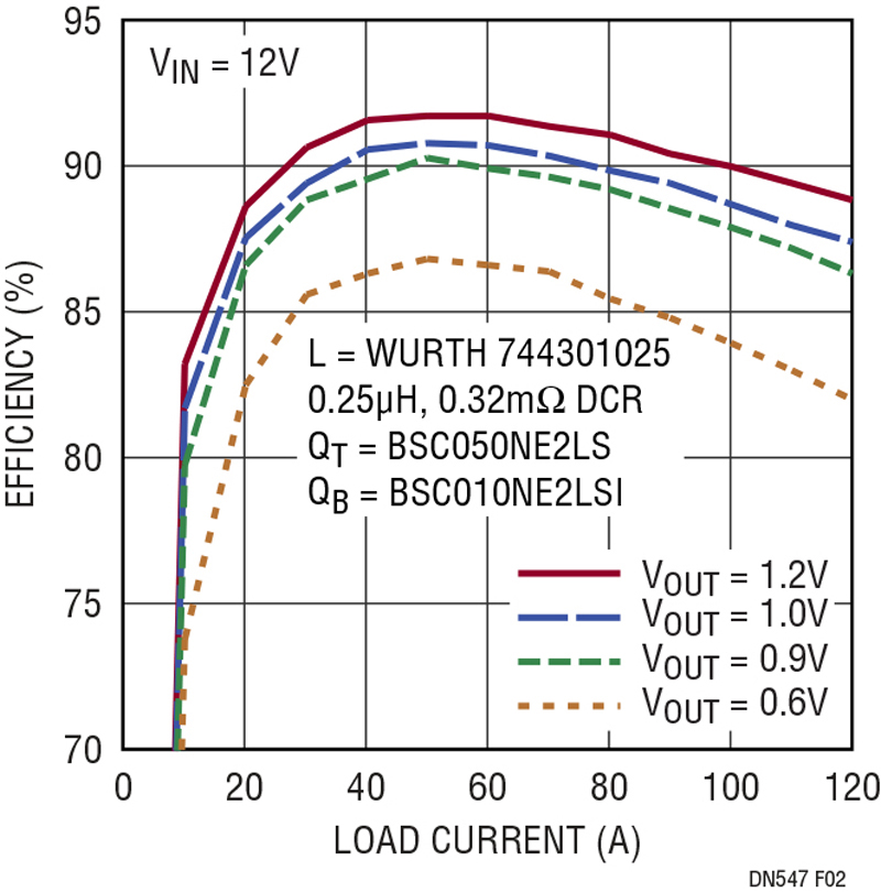
The full load efficiency for a 1.2V output at 120 amps is 88.8% and peaks to 92% at 60A as shown in Figure 2. This high efficiency is a result of the strong onboard gate drivers, short dead times of the two controller ICs, MOSFET selection and low DCR ferrite inductors.
Click image to enlarge
Figure 2. Efficiency of 4-Phase 120A VID Converter
The inductors used in this design have a wire resistance of 0.32 mΩ, resulting in the four inductors having a combined DCR power loss of (120A / 4)2 x 0.00032 x 4 = 1.2 watts, using the equation PLOSS (DCR) = I2x DCR x # of phases. A normal current mode controller, without the sub-milliohm DCR sensing feature would need an inductor resistance of at least 1mΩ, which results in a higher power loss of (120A/4)2 x 0.0010 x 4 = 3.6 watts. This lower resistance inductor design reduces the power loss by 2.4 watts and increases the full load efficiency by 1.3% when using it with a 1.2V output.
The LTC3877 comprises two current sense pins (SNSD+ and SNSA+) to acquire the inductor ramp voltage signal and processes it to provide a 14dB signal-to-noise ratio improvement to the low voltage sense signals. The current limit threshold is a function of the inductor peak current and its DCR value and can be accurately set from 10mV to 30mV in a 5mV steps. The part-to-part current limit error is only 1mV over the full temperature range assuring excellent accuracy.
In addition, the LTC3877 includes two differential amplifiers for applications that require remote sensing. Differentially sensing the load greatly benefits regulation in high current, low voltage applications, where board interconnection losses can be a significant portion of the total error budget. The LTC3877 uses a constant frequency peak current mode control architecture, it guarantees cycle-by-cycle peak current limit and excellent current sharing between power supplies phases. It is especially well suited to low voltage, high current supplies because of a unique architecture that enhances the signal-to-noise ratio of the current sense circuit. The improved signal-to-noise ratio minimizes jitter due to switching noise, which could potentially corrupt the signal.
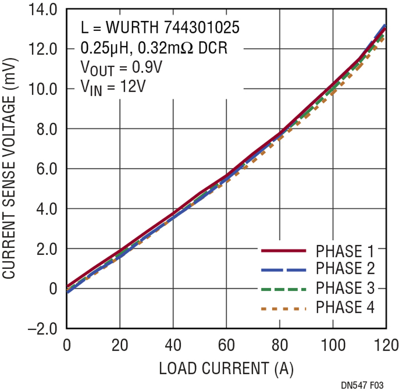
Both the LTC3877 and LTC3874 use a proprietary DCR current sensing architecture designed for sub-milliohm DCR sensing which allows for tight control of the current sharing and current limit. Figure 3 shows the current sharing performance of the 4-phase converter in Figure 1. The cur-rent sharing error is less than a 1mV between phases when sensing the voltage drop across the output inductors.
Click iamge to enlarge
Figure 3. Current Sharing of the 4 Phases with the LTC3877 & LTC3874
Improved performance
The LTC3877 allows the use of sub-milliohm DCR inductors in conjunction with its current mode control architecture for increased efficiency in high current applications. A current mode con-troller provides several benefits over a voltage mode controller of higher reliability with fast cycle-by-cycle current sensing, accurate current sharing between phases, simple feedback loop compensation and faster transient response.
The LTC3877 is ideal for high current point-of-load VID applications, typically found in the latest generation of FPGAs, and can easily support up to 30A/phase (total 60A). For higher power applications, adding the LTC3874 phase extender al-lows for an additional 30A/phase, for a total of 120A. Furthermore, the added efficiency gain minimizes the thermal design due to the reduced power loss of this converter combination.