Author:
Dr. Ray Ridley, President, Ridley Engineering
Date
03/21/2015
 PDF
PDF
Let’s explore the measured control characteristics of a Cuk converter with separate inductors, and with a tightly-coupled inductor. The coupled-inductor Cuk has fewer diverse transfer functions, but it is still a challenge to control over a wide range.
Cuk Converter with Separate Inductors
In the three articles of this series on Sepic converter measurements [2], it was shown that the sometimes-unpleasant converter control characteristics [1] could be tamed by tightly coupling the two inductors of the converter on one core. In this article, the same techniques will be applied to the Cuk converter operating over the same voltage ranges as the Sepic.
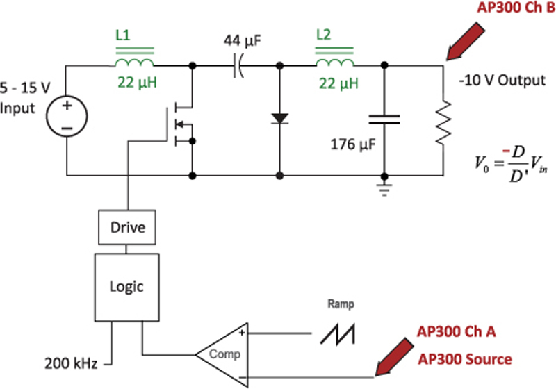
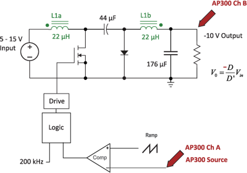
Like the Sepic converter, the uncoupled Cuk converter has fourth-order transfer functions, with up to three RHP zeros, depending on the converter operating point. Rather than just presenting complex control equations, the practical measurements on the Cuk are given. Figure 1 shows the schematic of the Cuk converter with discrete inductors, and all component values. The inductors are off-the-shelf parts, each with a value of 22 µH.
Click image to enlarge
Figure 1: Separate Inductor Cuk Converter with Control-to-Output Measurement Setup
Using the AP300 frequency-response analyzer [3], a signal was injected into the PWM modulator for the converter, and the gain and phase measured from the input to the output of the converter. The input voltage was varied from 5 V to 15 V to show the range of transfer functions for the converter. Figure 2 shows the results of these measurements.
Click image to enlarge
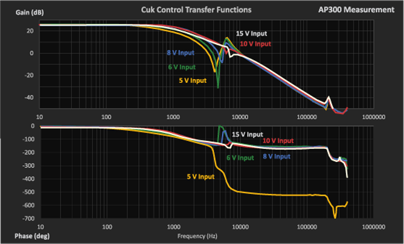
Figure 2: Range of Transfer Functions for the Separate-Inductor Cuk Converter
For all input voltages, the low frequency gains of the measured transfer functions were essentially the same. However, the characteristic varied substantially in the range from 4 kHz to 8 kHz, with an extra pair of RHP zeros appearing at low line, and high-Q LHP zeros at higher input lines. These moving zeros make the control of the converter extremely difficult over the full range, and the changing characteristics are a function of the parasitic damping of the circuit. One way to control this variability is with additional RC damping branches, but this yields a 6th order power circuit and the analysis becomes even more complex.
Cuk Converter with Coupled Inductors
In the previous articles on the Sepic converter [2], coupling the two inductors on the same core removed the difficult characteristics. This can also be done for the Cuk converter. It was shown that there was no significant difference in the control characteristics when tightly or loosely coupling the inductor windings. Since it is easier to build, tightly-coupled inductors were wound on a single core.
The schematic of the coupled-inductor Cuk converter with a single core is shown in Figure 3.
Click image to enlarge
Figure 3: Coupled-Inductor Cuk Converter
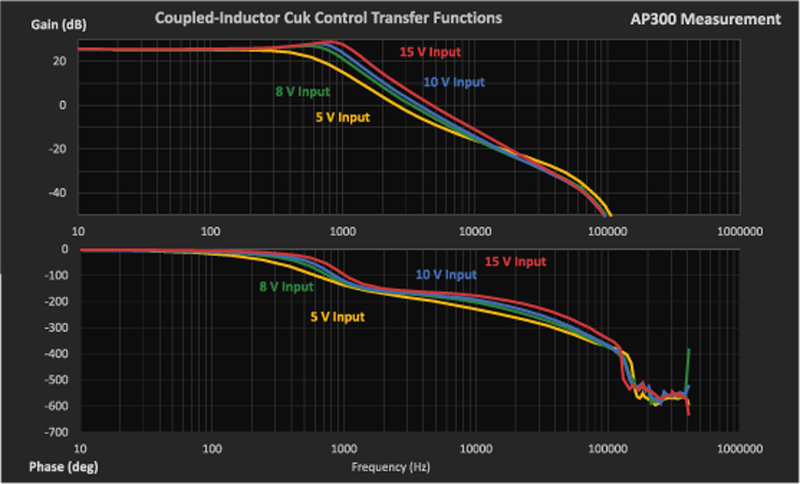
Figure 4 shows the range of the transfer functions with the coupled inductor. It can be seen that the difficult and variable characteristics shown in Figure 2 from 4 kHz to 8 kHz are completely removed. The couple-inductor Cuk converter is now about the same as the boost converter in terms of difficulty of control.
Click image to enlarge
Figure 4: Range of Transfer Functions for the Coupled-Inductor Cuk Converter
To make the final design of the Cuk converter even simpler, current mode control can be used. As was shown in the third part of the Sepic series in [2], the control loop becomes even more invariant with changing conditions when current-mode is used, yielding a converter that is much simpler to deal with in the compensation design.
Cuk Converter Efficiency
As with the Sepic converter, interesting effects were seen on the efficiency increase of the converter when changing from off-the-shelf to custom wound parts. This was mostly due to a different inductor structure, changing to a gapped ferrite from a powder material. Off-the-shelf inductors are usually optimized for cost, and you can often do better if you have more space or a different profile to work with. Being able to try your own custom magnetics is key to success, and you can learn more about this in [7].
The coupled-inductor Cuk converter has improved transfer functions over the non-coupled design. This article has shown the experimental measurements of the transfer functions in order to quantify the extent of the changes.
In either case, it is important to characterize the transfer function properly for the Cuk converter by making measurements over the whole range. The analysis is complex, and not always accurate due to the variability of parasitic elements. Measurements are always advised to show reality.
References
[1] “Sepic Converter Analysis Notes”, Dr. Vatché Vorpérian, www.ridleyengineering.com/design-center.html
[2] Sepic converter measurements, Parts I-III, Articles [80] – [82], Ridley Engineering Design Center Library, www.ridleyengineering.com/dc1.html
[3] AP300 Application Notes and Videos, www.ridleyengineering.com/analyzer.html
[4] Measuring high-performance loops, www.youtube.com/watch?v=CbjtGZtaUaQ
[5] Join our LinkedIn group titled “Power Supply Design Center”. Noncommercial site with over 5000 helpful members with lots of theoretical and practical experience. www.linkedin.com/groups?&gid=4860717
[6] See our videos on loop testing and power supply design at www.youtube.com/channel/UC4fShOOg9sg_SIaLAeVq19Q
[7] For power supply hands-on training, please sign up for our workshops at www.ridleyengineering.com/workshops.html