Pre-Charge Circuits in High-Voltage Systems
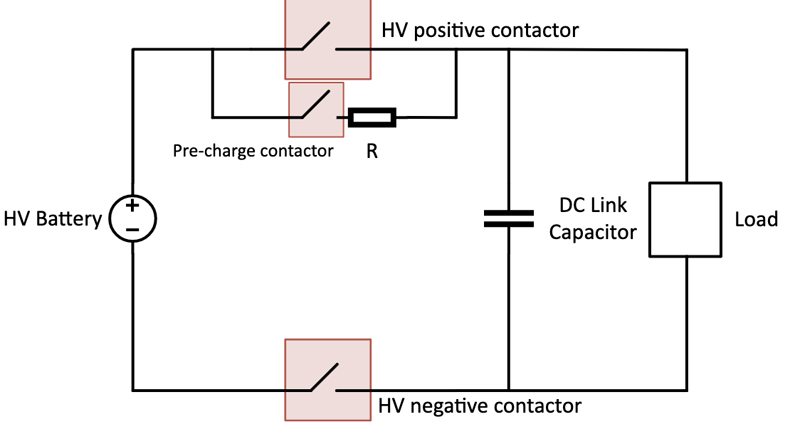
Figure 1: Pre-charge Initial State
An inrush current, also referred to as input surge current, or switch on surge, is the high current, which is often drawn when circuits are initially switched on. Power converters can have inrush currents that are many times higher than their steady-state currents. This is due to the initial charging current of the input capacitances of the circuit. Failure to manage inrush current can lead to damaged cables, connectors, or fuses. High-voltage systems (100V+) often use precharged circuits to limit inrush current. This process protects the system from damage, extends lifespan, and increases reliability. TPSI3050-Q1 is an isolated switch driver that drives external FETs to create a Solid-State Relay (SSR) solution. This solution can replace the mechanical pre-charge contactor while improving power density.
Applications and Benefits
Pre-charge circuits are often used in electric vehicles (EVs) such as battery management systems, onboard chargers, and in industrial applications such as power supplies and power distribution units. In EVs, controllers with high capacitive loads regulate motors. High voltage (HV) positive and negative contactors are used in this system to act as an emergency disconnect when the motor regulator fails. Without a pre-charge circuit, welding can occur within the contactor as it closes and there could be a brief arc resulting in pitting.
Pre-charge
In a high voltage system, a typical block diagram may consist of two high current contactors with a separate pre-charge contactor, and a DC link capacitor in parallel with a load (for example, traction inverter). Figure 1 through Figure 3 show the steps taken to pre-charge a DC link capacitor.
Click image to enlarge
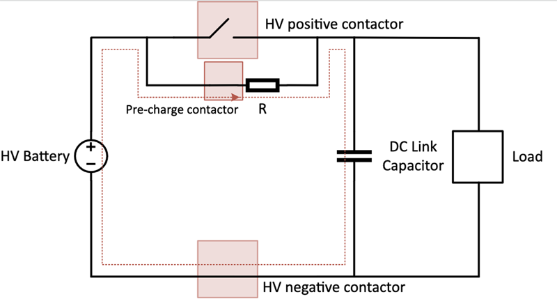
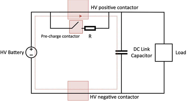
In Figure 1, the two high-current capable contactors, HV positive and negative, are open. The HV battery is disconnected from the load at both terminals and the DC link capacitor remains discharged. Pre-charging introduces a new state in the system, which we will call the pre-charge state. In the pre-charge state, the pre-charge contactor and the HV negative contactor are closed as shown in Figure 2. The DC link capacitor charges to nearly the same voltage as the voltage source. After the pre-charge state, the precharge contactor opens and the HV positive contactor closes to drive the system or charge the battery. Since the DC link capacitor charged before the HV positive and negative contactors were closed, there is no high inrush current and the system operates normally as shown in Figure 3.
Click image to enlarge
Figure 3: Pre-charge Steady-State
TPSI3050-Q1 Features for Pre-charge
The three main features the TPSI3050-Q1 provides is that it can perform as an isolated switch driver, disable switches quickly, and generate its own secondary bias supply. Each of these features provides benefits of increased flexibility, reliability, and smaller solution size.
· Isolated Switch Driver
TPSI3050-Q1 has the flexibility to drive external FETs or IGBTs to form a Solid State Relay solution, replacing mechanical relays or contactors. Compared to mechanical relays, SSRs are more reliable, lighter, and smaller in size. Since there are no mechanical moving contacts, there is no audible noise or physical circuit wear out. As a result, the TPSI3050-Q1 creates a reliable cost-effective isolation solution.
· Disable Switches Quickly
One key feature of the TPSI3050-Q1 is its ability to disable switches quickly. This can be useful to protect in events such as overheating or overcurrent. The response time of the TPSI3050- Q1 is less than 3us while relays are often in the range of 1-50ms (depending on the armature and force of the spring).
· Generates Secondary Bias Supply
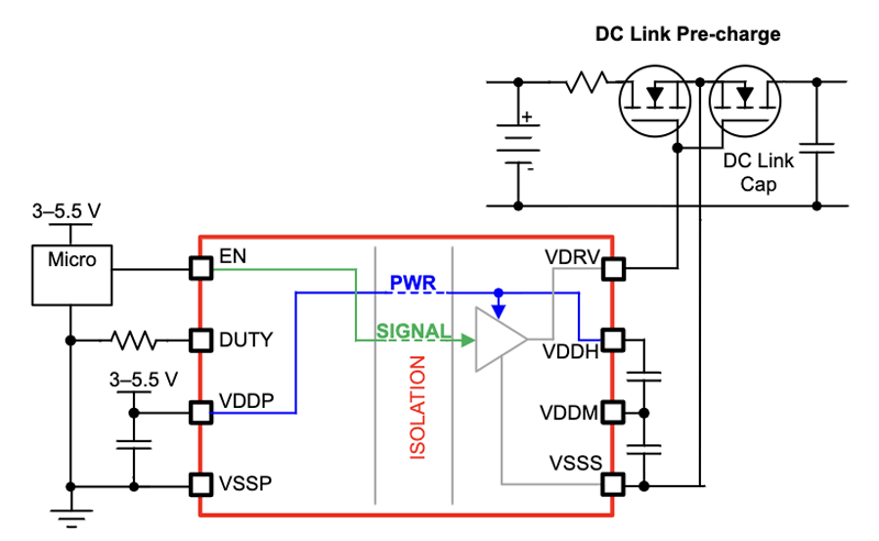
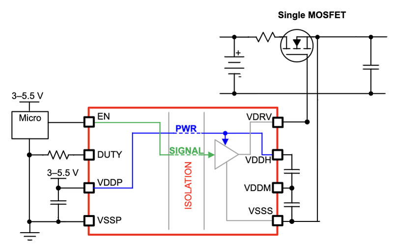
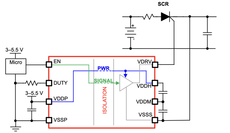
TPSI3050-Q1 generates its own secondary bias supply from the power received on its primary side. The secondary side provides a regulated floating supply rail of 10V for driving a variety of power switches shown in Figure 4 such as dual back-to back power switches for AC applications, single power switches for DC applications, various types of SCRs, and more.
Click image to enlarge
Figure 4a, 4b & 4c TPSI3050 in Application
TPSI3050-Q1 in High Voltage Pre-charge Circuits
Figure 4 shows the TPSI3050-Q1 connected to a pre-charge circuit that has MOSFET switches. In this example, TPSI3050-Q1 operates with an EN signal, and low voltage supply between VDDP and VSSP on the primary side. On the secondary side, the VDRV pin connects to back-to-back MOSFETs in a common source configuration. When EN pin is logic high, TPSI3050-Q1 will signal information from the primary side to the secondary side to assert VDRV high. Similarly, when EN pin is logic low, VDRV would be driven low.
Conclusion
A pre-charge circuit can be used to prevent stress and damage to the electric system by implementing a resistor and a switch to limit in-rush current. The TPSI3050-Q1 can replace traditional pre-charged contactors for a more reliable, smaller, and more responsive Solid State Relay solution compared to mechanical contacts which can wear out over time.