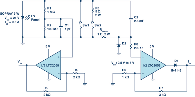
Figure 1. PV sweep measurement with the LTC2058
Photovoltaic (PV) modules are popular and affordable sources of renewable energy. Most photovoltaic modules last about 20 years, but thermal stressand moisture ingress, among other causes, can degrade a module’s output power over time. For the purpose of debugging, a module’s performance degradation can be measured by changes in its characteristic voltage-current curve.
Since the power output of PV modules varies widely with temperature, it is important to measure their performance in their typical operating environments. These are usually sunny, outdoor areas like rooftops or open, undeveloped spaces where it can be difficult to provide power to measurement equipment or to control the temperature.
Therefore, it is important that the measurement equipment used to characterize module performance does not drift with temperature. The idealI-V measurement solution would also be portable and use minimal power.
The LTC2058’s single-rail operation and shutdown mode allows forbattery-powered operation while maximizing battery life. Its dual amplifiers enable simultaneous measurement of two channels, such as current and voltage. For applications that experience wide temperature changes, such as PV module measurement, the LTC2058’s extremely low maximum input offset voltage drift over temperature of 0.025 µV/°C maintains its precision despite large operating temperature fluctuations. For example, an ambient temperature in a very sunny area could reach 45°C (113°F),
an extra 20°C on top of normal room temperature operating conditions. The maximum additional input offset drift contributed by the LTC2058 under that extreme condition is a mere 0.5 µV.
Measuring PV Module I-V Characteristics
A PV module’s characteristic I-V curve is produced by loading the PV module with a range of impedances from short to open circuits, andmeasuring the resulting current and voltage at each load. One method is to iterate through multiple settings of a high power rated potentiometer or load box and take measurements at each point. A drawback of this approach is that momentary shading or illumination, like a bird, cloud, or bright reflective object passing overhead, can cause transient dips or spikes in output power that introduce error into the I-V curve. A faster method is to throw open a parallel switch to a large capacitor, since the capacitor will effectively sweep its impedance from short to open as it charges over hundreds of ms, minimizing the chance that transient effects appear in the curve.
Beyond the obvious benefits of this method—namely speed, simplicity, and ease of measurement—using a transient capacitive sweep requires minimal high power rated components. Components are not subject to high power for more than a few hundred milliseconds. Thus, it is possible to use this exact measurement circuit for a wide range of module open-circuit voltages and short-circuit currents, such as in large area PV module testers, with the right choice of loading capacitor and sense resistor.
I-V Sweep Test Circuit for PV Panels Modules
Figure 1 shows an implementation of the I-V sweep approach to characterizinga PV module. C2 is the main capacitive load, where its size is a trade-offbetween measurement speed and accuracy: a smaller C2 sweeps faster, reducing the risk of error; a larger C2 sweeps more slowly and allows formore precise sampling of the measurement.
In the initial state, both SW1 and SW2 are shorted, so there is no voltage across C2. Both switches must be thrown open, first SW2 and then SW1, to start a measurement sweep that lasts 150 ms, ending with the full voltage of the module across C2. Discharging C2 after the measurementis done in preparation for the next cycle involves first throwing SW2 closed, where the 2 W rated R3 in series reduces the risk of sparking, and then throwing SW1 closed to provide a true short (RON= 0.3 Ω) across C2 and bringing the voltage across C2 to 0. For the purpose of full-systemimplementation, these switches can be power MOSFETs driven by digital signals that control the timing and sequence of switching.
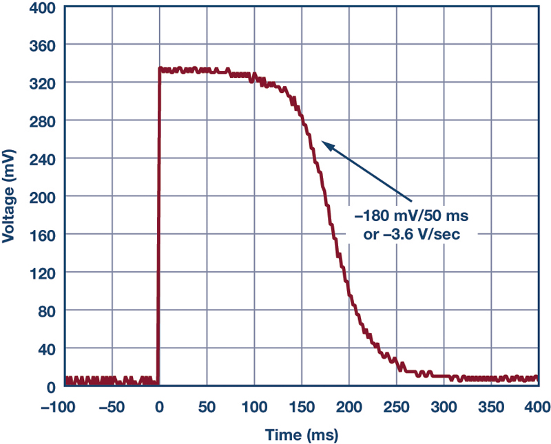
The LTC2058’s robust 2.5 MHz gain bandwidth product is crucial forprecise tracking of the sweep rate of the PV current through RSENSE. The greatest current sense measurement error occurs midway through the sweep cycle during the steepest transition. Although the input voltage across RSENSEhas a relatively low falling slew rate of 3.6 V/s (see Figure 2),the group delay of the op amp translates to real-time error in the current sense output. Also, since RSENSEis fairly large, the closed-loop gain for the current sense circuit can be as little as 4 V/V to produce a 2 V full-scale output at the maximum short-circuit current (ISC) of 0.5 A. This low gain is not a problem due to the LTC2058’s unity-gain stability. Thus, the LTC2058’s high gain bandwidth and low closed-loop gain requirement allow for a fast closed-loop response, minimizing the error due to group delay.
Click image to enlarge
Figure 2. Voltage across sense resistor with a slew rate of about 3.6 V/sec
The large capacitor C2, in conjunction with large RSENSE, determines the slew rate of the transition and thus the error due to a fixed delay. The trade-off of a larger C2 is that the I-V measurement takes longer.
The diode D1 allows the output of the current sense channel to swing all the way down to 0 V to measure the exact current at the open-circuitcondition at the very end of the sweep cycle. Diode D2 and 200 Ω resistor R8 help protect the current sense amplifier’s IN+from electrical overstress.
For the voltage sense channel, R1 and R2 divide down the full voltageof the module so that the output at VPV, after a closed-loop gain of 5 V/V, is within the 5 V supply rail. R1 and R2 can be adjusted to divide down any module open-circuit voltage (VOC), as long as they do not consumean appreciable amount of current relative to the module ISC. In this design, current through R1 and R2 contributes an error of 19 µA, or 0.0038% of ISC.
Click image to enlarge
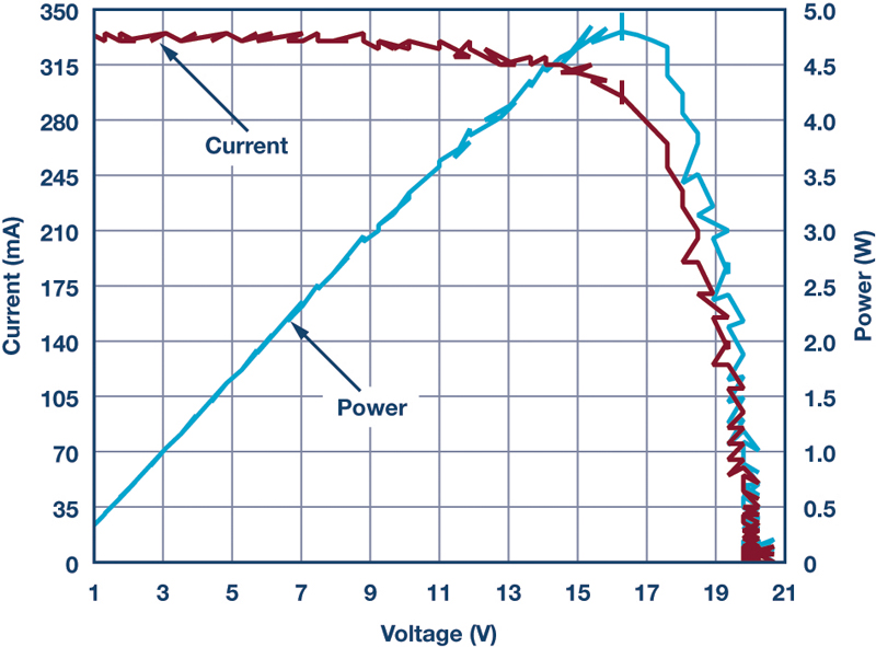
Figure 3. I-V and power-V curves taken with capacitive sweep and LTC2058 circuit
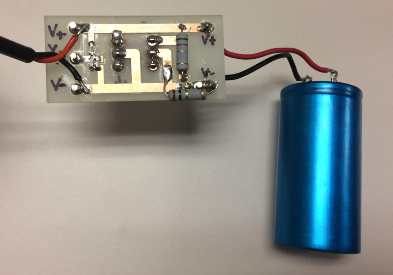
Click image to enlarge
Figure 4. PV capacitive sweep circuit; module connection on left, C2 on right
Conclusion
If a measurement device is located near a PV module, it will also be exposed to extreme ambient temperatures in environments such as cold,bright sunlight, or a hot desert climate. Yet it must maintain its precision in order to capture variation of the PV module’s performance over temperature. The LTC2058’s maximum average input offset drift over temperature of only 0.025 µV/°C enables precise measurement of solar panel performance under a wide range of temperatures.