Problems can cause increased jitter and sporadic operation
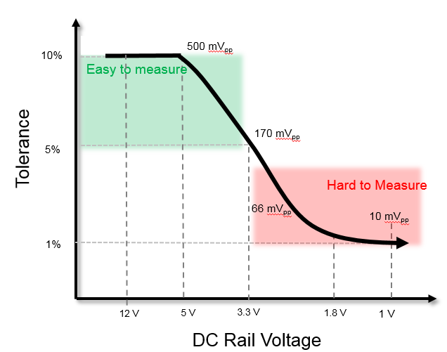
Development teams face increasing power integrity challenges. FPGAs, ASICs, and standard components semiconductor devices continue to increase in gate count. Each of the millions of gates on an integrated circuit requires current to switch. As devices can consume tens of amps and total power must be managed, DC rail voltages are forced to decrease. The ever-present move to higher speeds compounds the need to smaller voltages. Power integrity problems can cause increased jitter and sporadic operation. While DC power rails were predominantly 12V and 5V a decade ago, rail voltages have proliferated with the smallest at less than 1 volt. In addition, tolerances have decreased from 10% down to 1% to 2%. Lower rail values and tighter tolerances combine to require ripple and noise measurements of just a few mV in amplitude.
Today’s electronic products may include just a few, or in excess of a hundred power rails. Each one must be tested to ensure each DC supply is arriving at the pins of an IC with rail levels within tolerance. Oscilloscopes remain a primary tool for measuring AC attributes of DC signals including noise, ripple, and periodic and random disturbances. Traditional oscilloscope simply can’t make power integrity measurements with the accuracy required by today’s leading-edge electronic systems. Three key factors inhibit historical solutions: noise, bandwidth, and loading. To meet new power integrity measurement demands, several power rail probes specifically designed for power integrity measurements, have come into the market. These probes address issues that hinder traditional oscilloscope solutions, but requires additional upfront planning.
Measurement noise of traditional oscilloscopes and probing system makes it impossible to accurately make required small-amplitude measurements. The oscilloscope has inherent noise and when users plug in a probe, the probe adds additional noise to the measurement. The higher the attenuation of the probe, the more noise. Low noise measurements on small signals requires probing with 1:1 attenuation to minimal noise from the probing system. As a simple experiment, disconnect all inputs from the front of the scope and set the impedance to 50 Ω. Take a Vpp rms measurement to see how much noise the scope has. Now plug in a probe, connect the ground to the lead and measure Vpp rms. It will be significantly higher. All probes contribute to a dramatic increase in overall measurement noise, except for power rail probes.
On all scopes, noise is directly proportional to the total full screen scale. So, a vertical scaling of 100 mV/div, 1V with 10 divisions, will have significantly more noise than a vertical scaling of 5 mV/div, 50 mV full scale with 10 divisions. So, to further reduce noise, power rail probes ideally will let users scale down to the desired vertical sensitivities as low as 1mV/div.
Directly associated with vertical scaling is the ability for the measurement system to have adequate offset to scale the signal properly. For example, if a scope has a maximum offset of 1V and a user need to measure a 2.5V rail with 2% tolerance, only 1V of offset can be applied. So, to keep the full signal on the display, vertical scaling can only go to 500 mV/div putting the rail at the very top of 10 division oscilloscope. This doesn’t allow for making an amplitude measurement so the user has to adjust vertical scaling to 1V/div. At this sensitivity, the solution simply can’t make accurate ripple measurements for 2% tolerance. There is simply too much noise. Power rail probes come with increased offset capabilities. For example, the R&S ZPR20 has +/- 60 V of offset built into the probe. For the same 2.5 V power rail, the user can center on the scope’s display, and use a vertical setting of 5mV/div to minimal overall noise and increase measurement accuracy.
Click image to enlarge
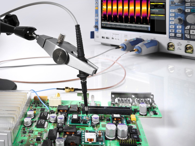
Figure 2. To meet the evolving needs of engineers making power integrity measurements with oscilloscopes, the industry has started offering active low-noise probes with 1:1 attenuation ratios. As an example, the R&S ZPR20 power rail probe offers 2 GHz bandwidth, 50 KΩ DCinput impedance, 1:1 attenuation and just 120mV of noise at 1 GHz bandwidth.
Having adequate bandwidth for measuring power rails may not come intuitively. How much bandwidth is needed to measure a DC rail? The answer is that power rails tend to be a conduit for coupled sources. For example, with close proximity to fast clocks and other sources, power rails often are subject to coupling the clock or clock harmonics. Wireless signals can be coupled on the rail. For these reasons, power rail probes need to have bandwidth in the multiple GHz range. Passive probes with 1:1 ratio can be useful for low-noise measurements, but are limited in bandwidth to tens of MHz and miss higher frequency transients. As an example, the R&S ZPR20 power rail probe supports a specified bandwidth up to 2 GHz to provide visibility of higher frequency coupled sources. The probe has a typical 3dB point near 2.4 GHz. While these higher frequency values will be attenuated, users still get visibility to coupled signals such as 2.4 GHz WIFI.
Loading is the third key issue addressed by power rail probes. DC rail impedance measures in the mΩ range. Some users may be tempted to directly connect their power rail to 50 Ω oscilloscope path. This creates a resistor divider network that ends up loading the rail and changing the rail’s DC value slightly. Not only will the measurement be incorrect, the slight change may impact the behavior of the circuit. To address the loading, a user may be tempted to use a 1MΩ passive probe. While this solves the loading problem, the passive probe will be noisy and will not have adequate bandwidth to capture transients. Active probing with high input impedance is required. Power rail probes accomplish this feat. As an example, the R&S ZPR20 power rail probe has an input impedance at DC that of 50 KΩ. This is 50,000 times more than the impedance of the power rail and will have minimal impact on loading. At higher frequencies, the active probe impedance is 50Ω allowing a perfect termination match with a 50Ω SMA cable and 50Ω pigtail coax.
Click image to enlarge
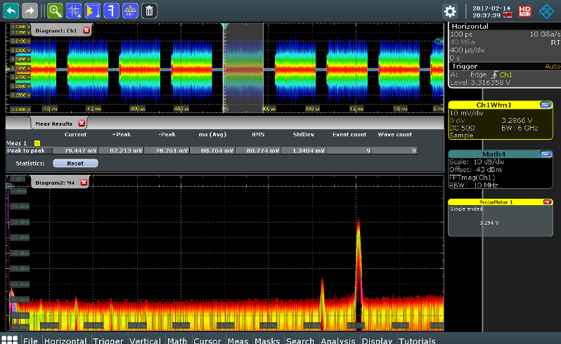
Figure 3. Coupled with an R&S RTE or R&S RTO oscilloscope, the R&S ZPR20 power rail probe allows users to quickly make time domain power integrity measurements. An FFT shows coupled sources.
Good probing includes high input impedance but doesn’t stop there. Power rail probes offer a variety of probing connections. For the most accurate measurements, users should plan on designing in an SMA connector on their device to route out DC rails that need testing. Alternatively, a 50 Ω coax pigtail can be soldered across a bypass capacitor and the coax connects to the power rail. These two methods achieve the lowest noise and highest signal fidelity. Hand probing using a browser with a ground spring can also be good, but is impacted by the ability of a user to touch and hold the probe while measuring. Longer ground connections create ground loops with inductive ringing and less accurate measurement results.
Power rail probes often include other nice features for simpler and faster power integrity measurements. One of these is the inclusion of a DC meter. For example, the R&S ZPR20 has an integrated R&S ProbeMeter that is a high accuracy DC volt meter that is independent of the oscilloscope acquisition system. The ProbeMeter allows users to quickly see the DC value without requiring the DC rail to even be on the oscilloscope display. Additionally, the measured value can be used to set offset eliminating the need to manually determine and enter the exact offset value.
A second nice-to-have feature is AC coupling. Turning on AC coupling has the negative downside of eliminating the ability to see drift, but can come in handy for users who want to quickly move from rail to rail and exclusively measure ripple and noise. Users can quickly move between different DC supplies without readjusting the offset compensation voltage.
Today’s power integrity measurements with decreased rail voltages and smaller tolerances require specialized power rail probes. With a low-noise 1:1 attenuation ratio, built-in offset, high bandwidth, and high DC input impedance, power rail probes enable engineers to make more accurate power integrity measurements on systems that have small rail voltages and tight tolerances.