Prevent Unexpected Shutdown by Accumulating Battery Facts

Monitoring devices can conduct high-accuracy measurements to provide a path to implement longer battery life strategies
Figure 1. Shutdowns can be frustrating
Individuals with annoying battery recharge problems become excruciatingly attuned to their device’s power meter because they know that battery mishaps or unexpected shutdowns can occur at any moment. Frequent battery recharging activities become a way of life and prevent some people from even leaving the vicinity of an AC plug (Figure 1).
Monitoring Through Time
Handheld tablets, smartphones, and notebook computers must multitask while providing the correct power consumption strategy for the end user. These multitasking events include peripherals such as wireless connectivity, human machine interface (HMI), cameras, and sensors. As time goes on, the challenge is to monitor and determine the power efficiency of each internal sub-system supply. The monitoring objective is to identify the sub-system supplies that consume large amounts of power and notify the user through the microcontroller or processor. This type of notification initiates a request to the user to modify the battery power usage (Figure 2).
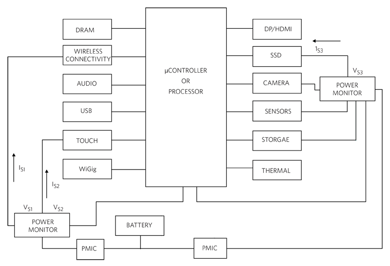
Click image to enlarge
Figure 2. Power Monitoring Applied to Multiple Peripherals
A power monitoring system is a network of power monitors that provide a circuit’s real-time sub-system supply data. These battery monitors take a “snapshot” of either the battery’s current consumption or voltage status, or both. Some monitors offload the system controller by calculating power values and storing the results over time. Either way, the power monitors send the data to an online processor or controller, allowing the system or users to identify potential problems.
Measuring Ongoing Power Consumption
The measurement of operating currents can capture sleep, data exchange events, and other general operational modes of the components in a sub-system supply (Figure 3).
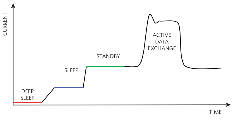
Click image to enlarge
Figure 3. Component Current Cycle Includes Deep Sleep, Sleep, Standby, and/or Active States (All Require Monitoring)
To estimate power consumption, the circuit’s complete load current, voltage, and power profile must be captured. This involves measuring not only sleep mode currents (in the range of nanoamperes to microamperes) but transmit load currents (milliamperes to amperes) and short-duration current bursts (microseconds to milliseconds).
Choose the Appropriate Monitoring System
The existing power monitoring trend is towards a distributed, controller, or processor approach where the power dissipation information is readily available. This basic configuration places the data-gathering monitors in strategic locations, such as peripheral power lines, critical-load branch circuits, and other areas. As shown in Figure 4, these monitors collect current (IS) and voltage (VS) data, calculate power (IS x VS), store data over time, and then send summary data back to the central controller or processor on a regular basis.
There are some general attributes that are important for this system. The monitoring devices conduct high-accuracy measurements, which ultimately provide a path for the user to implement longer battery life strategies. These monitoring systems quickly operate while efficiently collecting and calculating the power data.
Power Monitoring Data Collection
At the front end of the sub-system supply, the power monitoring system measures the sub-system supply’s current flow and supply voltage potential. A standard method for measuring battery current is through an external shunt resistor or RSENSE (Figure 4).
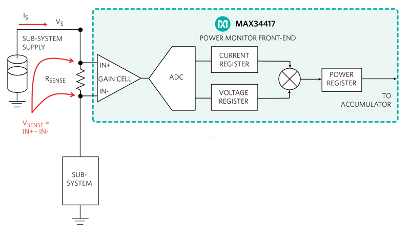
Click image to enlarge
Figure 4. Sub-System Supply Power Monitoring Function
The power monitor senses the voltage supply of the sub-system supply at the noninverting gain cell’s input (IN+) and current (IS) though a small shunt resistor (RSENSE).
The shunt resistor, RSENSE, translates the sub-system supply current to a voltage, which ultimately converts to a multi-bit word.
Equation 1 defines the value of the shunt resistor.
RSense = VSense
FSC
Eq. 1
Where VSENSE is the current-sense range and FSC is the full-scale-current.
Per Equation 1, 100mΩ would be the appropriate resistor for an FSC value of 1A and a VSENSE of 100mV. It is possible to purchase the small resistors that this formula renders but be aware that PCB trace resistance can become an error source for this delicate measurement. For example, every 1Ω of PCB trace resistance will add approximately 25μV of error.
To avoid this parasitic resistance error, the sense resistor configuration must have Kelvin connections. A Kelvin connection is a non-current-bearing PCB trace that senses the voltage of a node. Figure 5 suggests an appropriate Kelvin connection layout.
In Figure 5, the IN+ PCB trace connects between the resistor bond pads and the IN+ pin of the high-impedance differential pair. Conversely, the IN- PCB trace connects between the other side of the resistor bond pad to the IN- pin of the high impedance differential pair. In this way, the measurement of the sense voltage is directly across the sense resistor, without influences from other circuit board traces.

Click image to enlarge
Figure 5. Kelvin Connection Across the Shunt Resistor (RSENSE)
The MAX34417, shown in Figure 4, is a 4-channel power accumulator, which senses supply current and voltage and accumulates power calculations over time. The accumulation of current, voltage, and power measurements off-loads the controller or processor from the tedious task of continually monitoring and calculating the power of the sub-system supply. Based on the accumulator’s data, the system controller or processor collects the system’s power history and encourages the user to implement appropriate power consumption actions.
The power accumulation data allows users to identify system protection opportunities and optimize battery consumption. The device’s memory size holds up to 4.55 hours of accumulated data (at a data rate of 1024sps). This large memory size provides a significant off-load of the processor’s accumulator tracking and data collection duties.
Conclusion
We examined battery monitoring techniques, specifically focusing on the necessary sub-system supply measurements that prevent unexpected shutdown of portable devices. We then presented a unique solution using a power accumulator that monitors battery current and voltage activity. The substantial memory of a dedicated power accumulation device can mitigate the processor overhead traditionally needed for a power monitor. This provides a pathway that empowers the user to make better decisions based on power performance facts.
Maxim Integrated