Project Longhaul - an elegant expression of love and energy harvesting
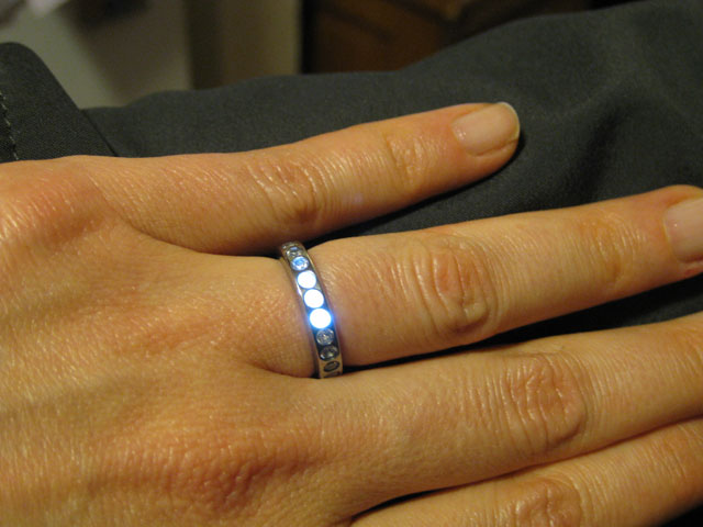
Editor's note: This is one of the most elegant, expressive, and technically advanced projects I have ever seen. It not only harnesses (pun intended) next-generation power-management technologies, it demonstrates the best in the harmonization of function, design, and execution. As a demonstrator of induction-driven energy-harvesting in a practical (jewelry is practical, ask your banker) product alone, it hits the ball out of the park, but it is also a beautiful example of state-of-the-art machining, electronic design, and their integration. Once upon a time, a boy met a girl. Then a short amount of time later, the boy decided to design and build a ring for the girl, because doing things in the most complicated way possible is just what he does to show the love. This is that story. It starts off in Jan of 2013 where the idea for the ring was refined to what will ultimately be the final form. Several designs were considered and were rejected because of exotic material requirements, machining geometry limitations or violating the laws of physics. It was a fun exercise to explore potential and unique designs, but at the end of the day, I still needed to make her something that I could present and that didn't look like it was carved with a spoon. The final idea was to embed a LED and copper coil assembly inside the titanium ring, illuminating it from under the stones when it was in close proximity to an induced alternating magnetic field (henceforth called 'the transmitter'). Autodesk Inventor helped me develop all of the dimensions and constraints for the design. Having some help, I was able to obtain her ring size and the rest of the measurements were based from there (15.72mm if anyone was wondering). Working with titanium was a little bit of a learning curve. Its harder than aluminum and steel which forces you to use carbide tools for any cuts. It is possible to use High Speed Steel tools but they wear out quickly, which will start to work-harden the cut. Someone with more experience could probably make it last longer, but I had to get this done! The ring start off as a bar of 0.875" diameter (apologies for mixing units) Titanium AL6V4. I face it off and turn down the external diameter to 19.8mm. This allows for 2mm of space on each side of the ring for all the features. The beginning Care needs to be taken to not overheat the drill bit (or any tooling for that matter). Titanium doesn't conduct heat well, so the heat will stay on the cutting edges of the tool. This puts the tool at a large risk for burn-up. As shown, this HSS drill bit died as a result of me getting it too hot and melting the outside cutting edge. First lesson to me: USE CARBIDE BITS The 23 stone mounts were drilled on a mill using an index table in a 3 stage process. Stage one is to use a 0.8mm spotting drill to pilot the holes. Once complete, it is now necessary to separate the ring from the barstock. If we do not do it at this stage, the walls of the grove created in the subsequent steps will collapse. A very small, thin and SHARP circle of metal accompanies the intended ring when it is cut off. Pro tip: not a good gift for children! Now it is necessary to form the internal space for the electronics package. I use a collet on the lathe to hold a the ring, and a match-fit mandrel to help keep it aligned. Using an o-ring grooving tool, I carve out a 2mm x 1mm cavity within the ring. The shelf will hold the strip of permalloy (which will be explained later) and the space will accommodate the coil/LED assembly. Creating internal space For reasons explained later, a slit will need to be cut into the ring. Cutting into a stone location will allow the stone to maintain the rings alignment, and keep it from bending. Should I have cut it between stone mounts, then it would be difficult to keep the ring from deflecting and causing a pinch point. A 0.006" saw was used to make the cut. Surprisingly, the slit saw was made from HSS, and held up really well. Remember to use your cutting oil, boys and girls! The last stage of metal working includes the base polishing. This was accomplished in 3 steps, using a microscope. Since I took care on the lathe and the mill to use sharp carbide tools, the residual scratching was at a minimal. I used a 1200 grit sandpaper to remove any scratches that seemed 'big' to that grit. Then with the help of my dremel and felt wheels, I used the yellow compound followed by the white compound (on separate wheels). I was pleased with the results after I washed off the residual compound. I used the Ryobi Hard metal cleaning compound P/N: A04HM01. Thorough washing was required, allowing for a clean surface to which apply an epoxy. I tried several attachment methods, but they all resulted in damaging the stones or ring. Since the holes were very close to the diameter of the stones, I opted to use jewelers epoxy (Epoxy 330, by Hughes Associates) to attach the stones to the ring. A holder was created to assist in this effort. The stones were mounted 8 at a time, allowing the epoxy to cure between mountings. A quick touch-up with the white-compound buffing wheel, and the metal portion of the ring is completed. The ring contains 13 white stones and 10 blue stones. Take note of the 'pin' stone at the location of the slit. This stone is under compression, helping it remain in its space. Creating the electronics packs was simple in theory. Create a coil of wire forming an inductor, add a capacitor and LEDs in parallel and TADA you have an inductive power receiver. To make sure that my wire and winding were aligned, I created a die with guides to assist in that effort. Coil winging die Winding was tediously performed on top of Kapton tape, providing a sticky surface to adhere the 40-gauge enameled wire and an insulating layer to the rest of the ring. The coil was measured to be approx 13uH. Adding in a 820pF capacitor brought my resonance frequency to approx 1.5MHz. ROHMs PicoLED series were used for the illuminators for their size and small power consumption. Heat resistant epoxy was used to affix the LEDs and capacitor to the kapton tape placed over the wire coil. Cutting transmitter circuit A stiff and thick gauge wire was needed to handle the high AC voltages(80V p-to-p!!)and to keep from deforming, causing field irregularities. I wound the wire around round-cut 4x4, using a softer wire to maintain the spacing consistency. Once I stabilized the coils, I covered the whole thing in epoxy and wrapped the external diameter in tape to hold in the epoxy while it cured. Constructing transmitter coil Soldering the large inductor coils to the transmitter circuit required a big iron and a lot of heat, but it didn't seem to damage anything. The board was attached onto an armband so that I could affix it to my forearm. The jacket test was to conceal the transmitter under the jacket so that it would illuminate when I got close to her hand. Initial tests show the field effectively coupling from the transmitter to the ring, illuminating the LEDs. A Permalloy core helps re-direct the magnetic field allowing for more of the field to couple into the coils of the ring. Care had to be taken while stuffing the coil into the ring. When I first tried it, I apparently forgot how induced magnetic fields cause currents within a metal ring, causing the field to cancel out of the intended inductor coil. This is why a slit is required in the titanium ring. I started this idea in January 2013, and presented the ring to my fiancée on May 2013. From the start, I had to learn AutoCAD, design and develop a circuit that would inductively couple power to the ring, and also how to understand the nuances of working with titanium. In that time, I made several test models and explored several options before coming to this design. The presented ring represents version 10 of the cut metal rings. The previous 9 models were stepping stones to understand behaviors, or test out theories of how to perform an operation. A good scientist knows to do qualitative tests! An extended version of this article with more images can be found HERE. Kokes dot Net