SEED modeling helps to develop automotive Ethernet ESD protection systems that meet OPEN Alliance specifications
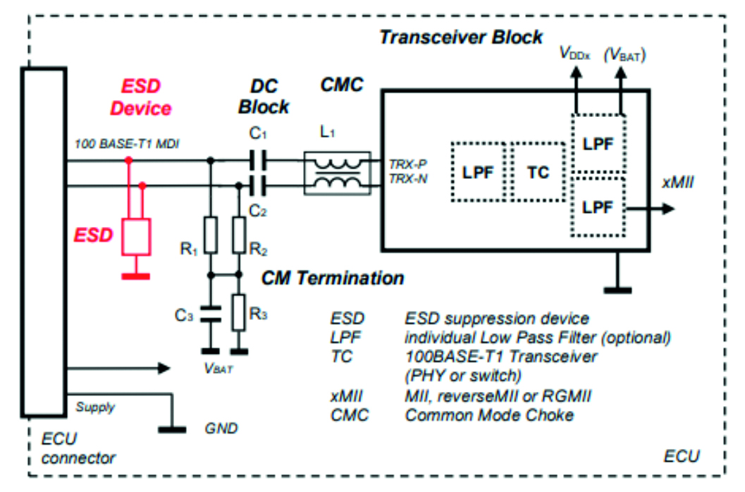
Figure 1: Arrangement of ESD suppression device within the 100BASE-T1 MDI interface, OPEN Alliance SIG (2019)
New trends in the automotive industry such as increased connectivity, electrification or autonomous driving are increasing the amount of data that must be transmitted around vehicles. This causes a corresponding increase in bandwidth requirements and existing protocols such as LIN, CAN-FD and FlexRay are no longer sufficient in a heterogeneous in-vehicle network. Automotive Ethernet will be the solution to handle data payload but new ESD protection devices are required to ensure safety. With System-Efficient ESD Design, (SEED), new system-level approaches to ESD simulation are being employed to develop new protection components that meet industry requirements.
As new applications and technologies will continue to significantly increase the data payload that needs to be managed and transmitted in the car, a startling prediction is that the cost of wiring harness and electronics is increasing and could shortly account for 40 percent of the cost of a car. Changing the wiring harness to a hierarchical homogeneous network and zonal architecture is expected to reduce cost and cabling weight but also supports rising demands of high data-rates, data security, and flexibility. Automotive Ethernet therefore becomes vital for this new network design to handle future requirements. To encourage the wide scale adoption and standardization of Ethernet-based networks, major automotive OEMs and Tier1 suppliers are collaborating as the non-profit OPEN (One-Pair Ether-Net) Alliance Special Interest Group (SIG). Moreover, security and reliability have become more an issue to ensure safe operation of networks. When it comes to system level robustness, discrete ESD protection devices as well as the system design take a crucial role and new requirements emerging with OPEN Alliance standardized Ethernet must be considered.
A fundamental ESD design challenge is the prediction of system level robustness. A general misconception is that system level robustness depends on the robustness of individual components. Instead, it depends on several factors:
- the robustness of the weakest device in the system (usually the SoC that is to be protected)
- the properties of the protection device
- properties of other elements in the signal path
- parasitic effects arising from the board and mounting wires.
The concept of System-Efficient ESD Design (SEED) is to consider all these parameters as an equivalent circuit or circuit-like simulation to predict system level robustness. An equivalent circuit representation of the system, including the SoC, is connected with a model of the protection device to evaluate protection performance. As well as SPICE-based simulations, other simulation tools such as Verilog-A and customized models based on network parameter blocks can be combined realize the system simulation.
One key goal of the OPEN Alliance SIG is to enable the deployment of the existing IEEE 100BASE-T1 and 1000BASE-T1 physical layer specifications with complementing specifications for conformance and interoperability. In previous automotive Ethernet implementations, PHY (physical layer interface, referring to the transceiver) vendors were advised to put any required discrete ESD protection device between the CMC (common-mode choke) and the PHY. Now, in the arrangement of ESD protection devices within 100BASE-T1 MDI network proposed by OPEN Alliance (Figure 1), the ESD protection device is placed immediately next to the connector, protecting not only the PHY but also the common-mode choke (CMC) and passives. Positioned thus, ESD strikes are directed straight to ground.
In its document ‘IEEE 1000BASE-T1 EMC Test Specification for ESD Suppression Devices’, the OPEN Alliance proposes a measurement called ‘ESD Discharge Current Measurement’ which gives an estimation of the overall system-level ESD robustness of the system. This test determines the residual current into the PHY1, identifying the ESD robustness class according to human body model requirements.
When developing industry’s first silicon-based, OPEN Alliance-compliant ESD protection for 100/1000BAASE-T1 automotive Ethernet systems, Nexperia used SEED methodology to replicate the ESD Discharge Current Measurement test. This simulation enabled the company to investigate how different parameters, including the parasitic inductance of the external ESD protection device, its trigger and snap-back behavior, influence the system level ESD robustness. This approach also enables developers to predict the levels of electromagnetic stress that other passive devices are exposed to during an ESD event.
Figure 2 shows the equivalent circuit block diagram of the SEED model for the ESD Discharge Current Measurement reference circuit. It consists of an external ESD device, the common mode termination (CMT) elements, a decoupling network, a common mode choke (CMC) and a 100BASE-T1 PHY (IC). This is realized in the test board shown in Figure 3.

Figure 2: The equivalent circuit block diagram of the SEED model for the ESD Discharge Current Measurement reference circuit
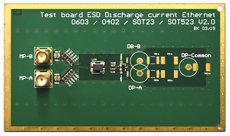
Figure 3: The test board
Whereas the CMC is a single device with an inductance (in this example) of 200 µH, the ESD device can be a single device which integrates matched ESD protection for both data lines (as in this example) or two separate devices each connected between GND and one of the data lines. The PHY is replaced by the ‘Transceiver Emulation Network’, thus retaining the electrical behavior during the ESD test. A 2 Ω resistor emulates the typical behavior of the IC internal protection in a simplified way, while the 50 Ω resistor minimizes the measurement effort of the IC current. The CMT network, located between the CMC and external ESD protection devices, consists of four discrete elements and two 100 nF capacitances are used for decoupling. The input of the test board is connected directly to the ESD device.
To reduce the modelling effort and accelerate the simulation process, a behavioral modeling approach is used. The model, tuned on the device’s typical static and dynamic characteristics, is implemented as an equivalent circuit consisting of lumped elements, controlled sources and feedback loops, and S-Parameter blocks.
Figure 4 shows a good match between simulated and measured time domain current curves in both first and second peak regions for a 2 kV discharge. Following this, each element of the SEED model - Decoupling and Termination Network, CMC, and ESD protector – can be evaluated. Figure 5 shows the measured and simulated performance for the external silicon based ESD protection lean on peak voltage and current of 1 ns rise time TLP pulses. After this, the complete system model (Figure 2) was validated against measurements taken from the reference board with and without external ESD protection using TLP. The TLP graph of a reference board with external ESD protection Figure 6 compares measured results and simulation results using SEED, demonstrating an extraordinary degree of congruence, showing that the implemented SEED model is fully suitable not only for qualitative but also quantitative prediction of overall system-level robustness.
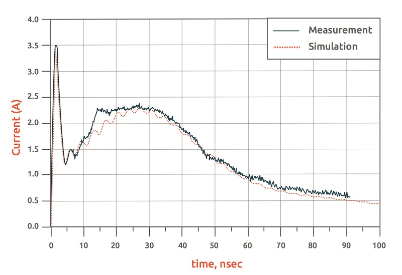
Figure 4: The match between simulated and measured time domain current curves in both first and second peak regions for a 2 kV discharge
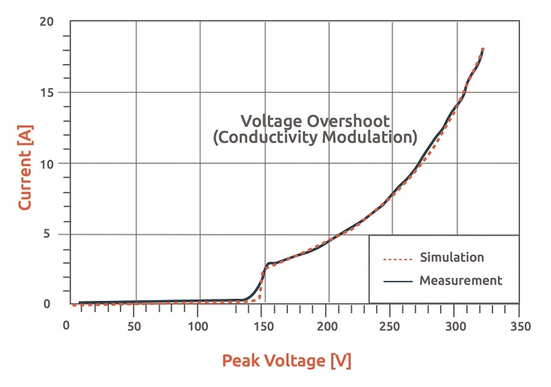
Figure 5: The measured and simulated performance for the external silicon based ESD protection lean on peak voltage and current of 1 ns rise time TLP pulses

Figure 6 compares measured results and simulation results using SEED
An ESD strike may occur when a person touches the GND or I/O pin(s) of the system board connector. This is replicated by injecting ESD pulses according to IEC61000-4-2 [9] into the system. Again, results of the SEED-generated simulation showed close agreement with the observed measurement. Using this approach, Nexperia - is a technical member of the OPEN Alliance SIG - has developed the first true OPEN Alliance-compliant ESD protection for 100/1000BASE-T1 Ethernet. Silicon devices offer a significantly higher level of protection - up to 30 kV system level robustness – than older technologies such as varistors, which are also subject to degradation over time. Available in low-cost, small, SOT23 surface-mounted plastic packages, PESD2ETH1G-T and PESD2ETH100-T ESD protection devices are the first choice for modern automotive Ethernet interfaces.
 Single.jpeg)