Integrating multiple functionalities into one module requires high-current protection in the event that things go wrong
Automotive manufacturers are increasingly incorporating higher-power, higher-inrush current applications – including anti-lock braking system (ABS) modules, glow plugs and engine cooling fans – into their latest-generation cars. A popular trend is to integrate multiple functionalities into one module, which in turn requires high-current protection in the event that things go wrong, such as when a thermal event occurs and leads to warranty and safety issues. Stemming from this need for manufacturers to protect consumers, automotive designers must comply with the AECQ vibration test and other automotive standards that mandate the use of thermal protection devices.
The Need for Protection
A resistive short is a fault condition that produces severe temperatures through I2R heating caused by the device’s resistance rising too high. A resistive short can harm automotive electronics systems in the event that power FETs, capacitors or other power components fail due to increased resistance, thus causing thermal runaway. As little as 10W may generate a localized hot spot of more than 180°C, potentially damaging the board’s epoxy structure. Moreover, there may not be enough current to open the upstream fuse.
The key drivers in the automotive market to use thermal protection devices are:
• OEM requirements
• High power density applications from 20A to 120A, steady state, and high-inrush current
• Applications permanently connected to +Vbat (battery supply)
• Harsh environment of the engine compartment (e.g., high temperature, thermal shock, corrosive products (e.g., antifreeze, braking liquid , gasoline) that can increase the chance of fire propagation)
• Design on an FR4 epoxy PCB
• Uncoated PCB, leading to higher risk of oxidation
• Customer quality department requirements (i.e., insurance)
• Help in meeting functional safety automotive standards, such as ISO 26262 ASIL D
High-current automotive applications, such as high-functionality modules, are particularly sensitive to adverse thermal conditions. Due to a variety of causes, a control module in a vehicle might be exposed to a voltage spike that is capable of “killing” the drain-to-source channel. The output gate driver of the power FET might fail in an abnormal condition or some type of wear-and-tear may cause the contact to become oxidized, leading to an increase in the gate resistance of the power FET.
When the gate voltage is close to Vth, the semiconductor works in a linear mode that can drastically impact the dissipated power and the internal temperature. For these reasons, it is necessary to provide extra thermal protection on board in case of power FET damage. Moreover, in new vehicle architectures, some ECUs (electronic control units) are permanently connected to +Vbat, which can increase the risk of a thermal event.
Reflowable Thermal Protection
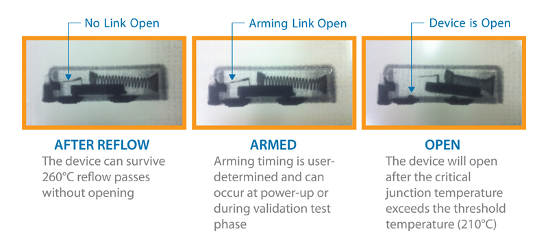
The HCRTP device was introduced in response to the growth of higher-power, higher-current automotive applications and the need to protect them. The innovative approach of the device is its ability to utilize a one-time electrical activation process to become thermally sensitive. Prior to activation, the device can withstand lead (Pb)-free solder reflow processes up to 260°C without opening. But following installation, the one-time electrical arming process initiates a lower thermal threshold of 210°C. After arming, which is typically done at end-of-line testing after reflow, the HCRTP device will open when the critical junction exceeds the 210°C open temperature.
No other similar device offers the same number of necessary features to meet OEM protection requirements. The device is automotive-grade (AECQ) qualified and compatible with SMD (surface mount device) reflow processes, which results in low assembly costs and can result in high reliability; it is housed in a very-low-profile (3.7mm max.) package, allowing it to fit into a miniaturized glow plug’s PCB; it exhibits a typical 210°C opening temperature, making it suitable for under-the-hood applications; it has a high operating capability with a nominal forward current of 90A at 23°C / 45A at 140°C, a preferred feature for integrated module applications; and, finally, it offers low resistance (approx. 100µOhm), which results in lower dissipation and voltage drop.
The HCRTP device can withstand hold currents of up to 90A at room temperature (23°C) and 45A at 140°C. Because the HCRTP device is a SMD component, performance of the operating current in steady state depends on the PCB layout and thermal management of the board. The low-profile device can be installed using industry-standard, Pb-free, SMD assembly and reflow processes. In comparison, radial-leaded thermal fuses must be installed after reflow, which can lead to additional assembly costs and reliability issues.
How it works
As shown in Figure 1, the HCRTP device uses an electronic arming mechanism. Electronic arming must be done after reflow, and can be done during final test. Sending a specified arming current through the ARM pin of the device arms it. Arming is a time- and current-dependent event. Current can flow in either direction through the ARM pin. Once “armed,” the device will permanently open when the device junction achieves its specified opening temperature.
Click image to enlarge
Figure 1. The arming mechanism of the HCRTP device
ABS
New vehicles are increasingly offering state-of-the-art ABS modules that integrate an electronic stability control or program (ESC/ESP) as well as an electrical parking brake (EPB) system on the same board. Although it enables design cost savings for the entire vehicle’s architecture, this integrated approach also increases component density on the board and, combined with increased power, can lead to catastrophic failure.
Many European OEMs require that irreversible thermal protection be placed as close as possible to the input connector to avoid thermal propagation outside of the vehicle when the inside module temperature reaches more than 200°C. In a typical automotive application requiring thermal protection, a current fuse is placed in the car’s junction box. The assumption is that if a thermal runaway event occurs, the current fuse will “blow” and solve the problem. This assumption is incorrect, however, since a thermal device is needed in addition to a current fuse to provide adequate protection.
As an alternative to typical protection approaches in ABS modules, the HCRTP device can be installed near the input connector in two in places on the board. In each instance, the HCRTP device acts as a last-defense solution to help protect the module from thermal runaway, which means that the car itself will need repairs from any damage caused by the condition.
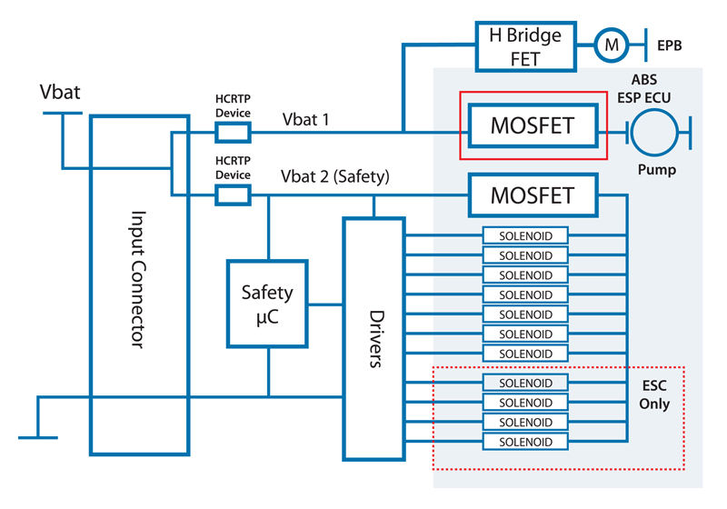
In an ABS application, redundant power lines are required for safety reasons. For integrated ABS platforms, HCRTP devices can be used in two areas to help provide thermal protection: the valves/solenoids and the oil pump motor. As shown in the block diagram in Figure 2, one HCRTP device is placed near the input connector on the board (“Vbat1”). A second HCRTP device is placed on the power line (“Vbat2), which is dedicated to supplying approximately 20A rms of current to the safety microcontroller unit and solenoids. In this example, both HCRTP thermal devices are near the input connector for last-defense on the board to mitigate damage from a power FET failing due to a resistive short.
Click image to enlarge
Figure 2. Two HCRTP devices are placed on the board in an ABS application: one on the safety µcontroller and solenoids (Vbat 2), the other near the input connector (Vbat1)
HVAC and engine cooling fan
Compared to using low-end brush motors without embedded ECU control units, medium-end cooling fan motors, or HVACs, which now include more (pulse width modulation ( PWM) control systems for speed regulation purposes, are increasingly preferred by automotive manufacturers since they help reduce carbon emissions; for example 2g/km for brush DC (BDC) motors and 5g/km for brushless DC (BLDC) motors. Other benefits include optimized variable speed control and a medium efficiency rate of more than 60% for brush DC motor and around 80% and more for BLDC. Furthermore BLDC motors can offer improved lifetime.
Designers are mandated to protect these automotive systems from thermal runaway. For example, according to the VDA requirements of the German Association of the Automotive Industry, thermal destruction of the engine and the engine’s cooling fan electronics must be prevented in all cases. This protection must be implemented by using irreversible safety equipment, which switches off the power of the motor, without an additional control circuit requiring current and voltage.
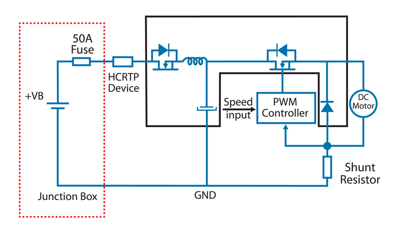
Figure 3 shows how an HCRTP device can be used to help provide thermal protection in a medium-end cooling fan motor or HVAC with PCB and embedded electronic components. This example shows a brush motor type system with a power range up to 600W. As shown, the HCRTP device is typically placed near the input connector for reverse-polarity FET protection and EMI filter. In this example the devices are also being used to help provide reverse-battery FET protection in case of thermal runaway.
Click image to enlarge
Figure 3. HCRTP device used in a brush DC motor with a power range up to 600W.
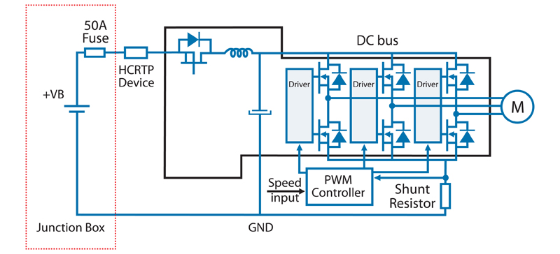
The next example, Figure 4, shows a high-end cooling fan motor with PCB and embedded electronic components; this brushless motor type has a power range up to 1000Watts. In this example the HCRTP is placed near the input connector to help provide FET reverse polarity protection in case of thermal runaway.
Click image to enlarge
Figure 4. HCRTP device used in a BLDC motor up to 1000W.
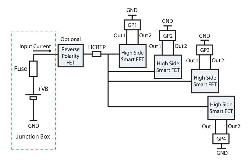
Glow plug
The sophistication of today’s modern engine management systems is driven by strict governmental regulations mandating increased fuel economy and engine performance, while also lowering harmful emissions. This has driven the industry to develop improvements in diesel direct-injection engine control systems and glow-plug controls. The trend is to replace conventional architecture using bladed fuse and relay with electronics switch built around semi-conductor devices such as a power FET.
In a four-cylinder, glow plug module, as shown in Figure 5, the electronic relay plug is directly connected to the +Battery. There is no relay (galvanic insulation) in between the electronic glow plug and lead acid battery, making the system more sensitive. The block diagram shows how an HCRTP device can be placed near the input connector to help provide reverse-polarity FET protection in case of thermal runaway. Again this approach offers last-defense protection on the board to help prevent thermal propagation.