Rapidly Advancing Automotive Technologies Create New Challenges for RF Test and Measurement
RF electronics technologies such as automotive radar have created safer, more efficient connected vehicles. They have also created new challenges for RF testing
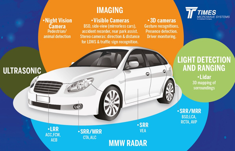
Figure 1. New automotive electronic systems
Automotive electronics technology continues to advance at an astounding rate, taking advantage of many of the technologies developed for aerospace, space systems, and the military. In a short amount of time, the industry has moved from basic gauges that monitor automobile systems such as fuel, speed and temperature to connected cars and autonomous driving.
With increasing complexity and advancement of automotive systems, more, radar systems are needed to power them. Automotive radar sensors use RF to detect the speed, range and angle of objects in the automobile’s vicinity in complex and safety-critical applications such as advanced driver-assistance systems (ADAS) and autonomous driving.Automotive radar components can be used for:
· Collision avoidance
· Automated braking
- Pedestrian detection/avoidance
- Parking assistance
- Blind spot detection
- Rear collision warning
- Adaptive cruise control
- And more
These automotive radar systems operate primarily in 24 GHz and 77 GHz bands, with a smaller percentage using 79 GHz. Many new applications are moving away from 24 GHz to 77 GHz due to the wide bandwidth available in that band. Wider bandwidth increases range resolution and accuracy by up to 20x in some applications and permits the use of higher frequencies with shorter wavelengths that enable smaller form factors. In fact, the ultra-wide band version of 24 GHz automotive radar is being phased out completely in Europe and the U.S. by 2022 due to spectrum regulations and standards developed by the European Telecommunications Standards Institute (ETSI) and the U. S. Federal Communications Commission (FCC).
Testing of Automotive Radar Modules
Automotive radar sensors utilize continuous wave (CW) radar with a continuous signal for detecting non-stationary targets. This requires two antennas: one for transmitting the signal and the other for receiving it. The transmitting antenna sends out radio waves that hit an object and bounce back to the receiving antenna to determine the object’s distance, speed and direction.
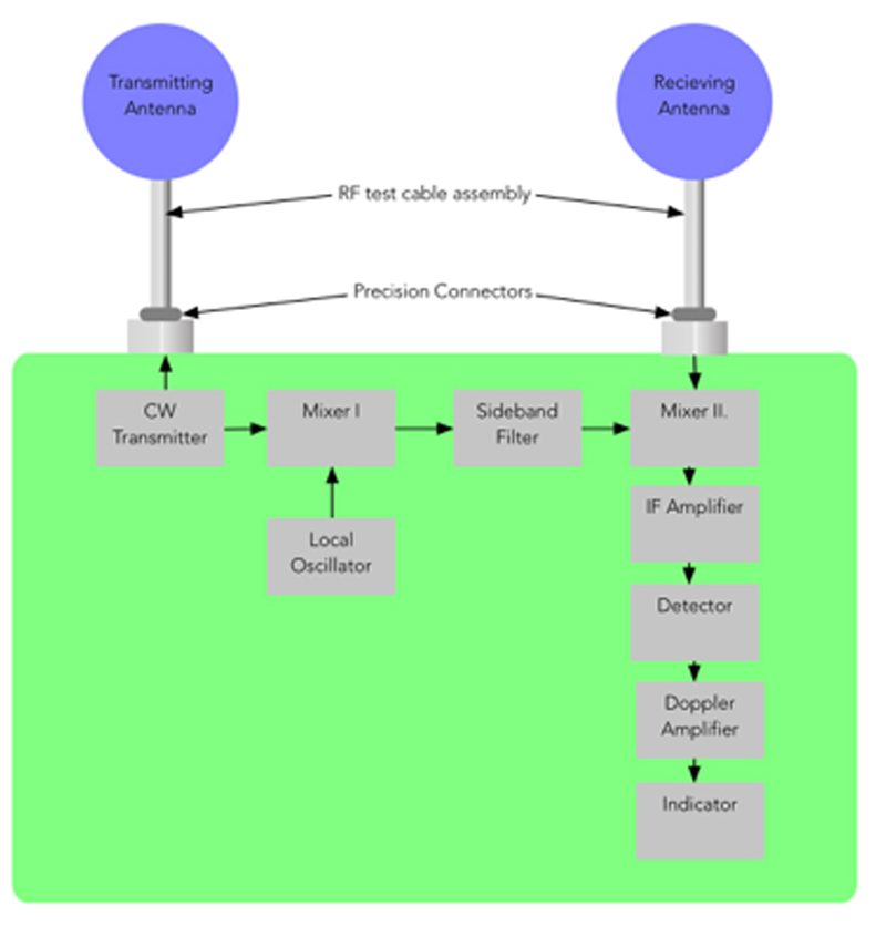
Click image to enlarge
Figure 2: CW radar system architecture
Automotive radars operating in the 77 GHz or 79 GHz band make use of linear frequency modulation (LFM) or frequency-modulated-continuous-wave (FMCW) technology. This type of modulation is called a “chirp.” The linearity of chirp waveforms is an important performance parameter as any nonlinearity, or frequency distortion, will distort the measurement. However, the possibility of interference among the systemsoperating in the same portion of the frequency bandcan increase potential for failure as an increasing number of automotive radar sensors are used in the connected vehicle.
As automotive radar systems are used to power safety-critical applications such as ADAS, it is critical to ensure quality and the correct operation for regulatory compliance. Robust test and measurement procedures are required.Testing against various interfering signals helps to verify the functionality of these safety-critical systems operating in extremely demanding RF environments. RF test cables that have the frequency range to fully identify these distortions allow the designer to make changes based upon those measurements.
The ability to test these components and systems at not only their fundamental frequencies, but at their harmonics, is key. In the case of components operating at fundamental frequencies of 18 GHz, 22-28 GHz, and 33 GHz, it is necessary to characterize these components at the 2nd and 3rd harmonic frequencies:
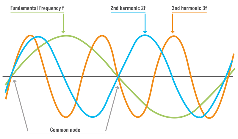
Click image to enlarge
Figure 3: Typical automotive RF component fundamental and harmonic frequencies

Click image to enlarge
This often lands at the 67 GHz range. Having the necessary equipment to accurately test at this frequency range is paramount.
Challenges for RF Test Cable Assemblies at 77 GHz and Beyond
Rapidly advancing automotive technology increases the complexity of test setups, requiring more test leads and connection points than ever before along with new RF testing challenges and requirements. As a result, it’s necessary to revisit the way connection points and test leads are built and review the different types of connectors available—while ensuring that the latest test assemblies work in concert with changes made by test equipment manufacturers.
Consequently, automotive RF testing requires unique coaxial cable and connector solutions. The typical RF testing process involves a device undertest (DUT) connected to a vector network analyzer (VNA), oscilloscope or spectrum analyzer. The signal path from the instrument to the circuit board is critical, and the test setup must not introduce unwanted variables orerrors, VSWR spikes, or excessive insertion loss. This includes the test cable assembly, cable, and connectors.
In addition, stability is essential as automotive radar deals with higher frequency ranges. For example, any type of inconstancy in connectors can introduce errors in the measurement, which is amplified as the frequency range of the test is increased. Cable assemblies must be durable enough to withstand extensive handling and continuous movement from frequent connecting and disconnecting, while maintaining precise repeatability of measurement and reliable electrical performance.
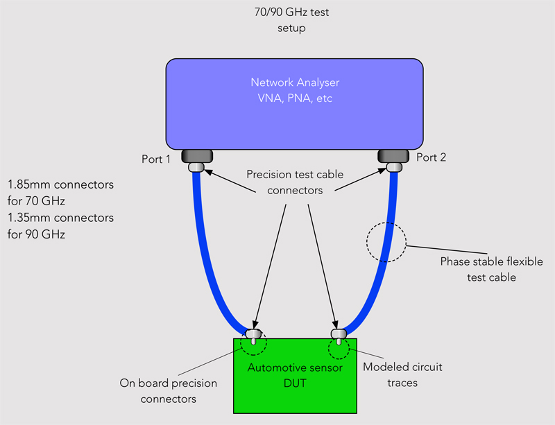
Click image to enlarge
Figure 4: The above diagram shows a typical setup for testing automotive sensors at various frequencies. The tests were performed at the fundamental as well as the harmonics to provide a clear indication of how the device will perform in the vehicle.
Evolving Requirements for Automotive RF Test Assemblies
Higher Frequency Ranges
As discussed, many previous automotive RF systems worked in the lower GHz range, but new technologies such as automotive radar sensors are pushing that up to higher frequencies, as well as spanning different spectrum bands. Cables and connectors that may have been used before will no longer perform in these higher frequencies.
To push the bandwidth into 77 GHz and beyond, millimeter-wave test cables, adapters and board-level interconnects will be required that can accommodate higher bandwidth without compromising signal integrity.
Flexure
Automotive applications are often tested in a production environment, moving from one module to another. In high frequencies, recalibration could be required every time a module or cable is moved. Using a cable that can bend and flex in both R&D and production environments will maintain stability and greatly reduce the need for recalibration.
Phase Stability
Constantly moving the cables around also affects phase stability. Movement introduces phase change, and the test assembly must maintain a very low rate of change to obtain accurate measurements. A robust cable is therefore critical to keep phase as stable as possible.
Additionally, when testing technologies such as automotive radar, the source and receiver might be running at two different frequencies at the same time. A phase-stable assembly will further ensure that harmonics are not introduced back into the system. A cable assembly utilizing a TF4 dielectric, coupled with a helically wound metalized interlayer, is recommended to maintain a flexible, phase-stable test assembly.
Amplitude/Low Loss
When a signal transitions from the circuit board to the connector, it is imperative to minimize reflections as much as possible. At higher frequencies, imperfections in the transition from a coaxial connector to a circuit board structure become more apparent.
These imperfections can cause parasitic and spurious signal responses. They manifest in either return loss or insertion loss, spikes, and magnitude increases, all of which are undesirable. If the signal integrity is off and there is noise in the measurement, the test will not produce an accurate device reading. To ensure high-fidelity measurement, a very repeatable, low insertion loss cable that functions throughout the desired frequency range should be used.
New Solutions for Mitigating Tough Automotive RF Testing Challenges
There are new test cables designed specifically to accommodate the higher frequencies required for automotive systems, 5G, and other advanced testing.This new class of test leads offers a very repeatable, low insertion loss cable that functions throughout the desired frequency range to ensure a high-fidelity measurement, with specific options available that cover 70 GHz to 90 GHz, as well as up to 110 GHz if required. Created for precision and stability, thisphase-stable cable assembly utilizes a microporous PTFE dielectric, coupled with a helically wound metalized interlayer, to maintain a flexible, phase, and amplitude stable test assembly.
This type of RF test cable contains flexure in a very robust package for accurate measurement and features a stainless-steel barrel type boot and a large 1.35-mm connector selection. Automotive designers should partner with a manufacturer with fully integrated design, production, assembly and testing capabilities for customized solutions to meet the most demanding automotive testing requirements.