A number of significant electrical performance improvements are evident using high-value MLCCs
Advances in multilayer ceramic capacitor (MLCC) technology now offer designers a high-capacitance alternative to traditional electrolytic capacitors. New high-value MLCCs provide the advantages of lower equivalent series resistance (ESR) and inductance (ESL) than electrolytics, and demonstrated mean time to failure (MTTF) in excess of 10,000 years. Comparisons of performance demonstrate the potential for MLCCs to displace polymer capacitors in designs that require high-capacitance values and/or other system-level improvements.
Performance comparisons
Aside from the mechanical advantages that the solid-state nature of the MLCC topology provides in comparison to electrolytic devices, a number of significant electrical performance improvements are also evident.
Lower ESR and ESL
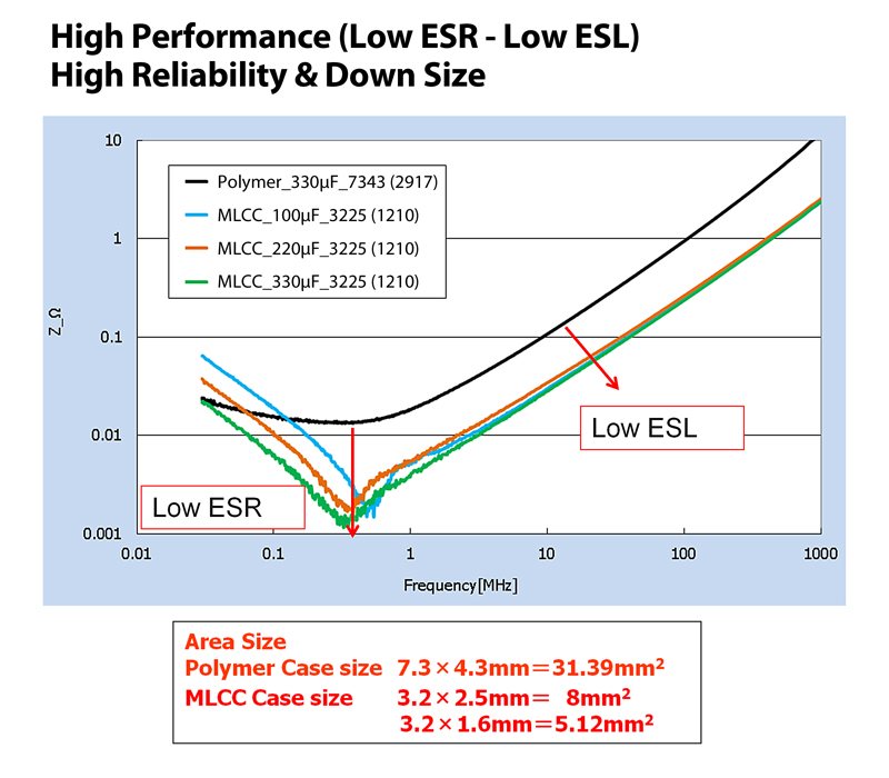
Figure 1 shows the lower equivalent series resistance (ESR) and equivalent series inductance (ESL) of 100µF, 220µF and 330µF MLCCs compared with a 330µF polymer capacitor. In addition to the reduced system losses from lower ESR and ESL values, the case size and printed circuit board footprint of the MLCCs are dramatically smaller as well.
Click image to enlarge
Figure 1. MLCCs of 100µF, 220µF and 330µF compared with a polymer capacitor
Comparable ripple performance with smaller case sizes
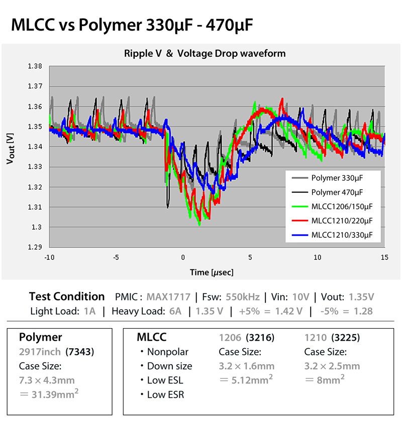
Figure 2 shows the ripple voltage and voltage drop waveforms of 150µF, 220µF and 330µF MLCCs compared with 330µF and 470µF polymer devices. The ripple voltage of the 150µF MLCCs is similar-to-slightly-improved compared with polymer devices, and with the 220µF and 330µF MLCCs ripple performance is significantly improved. Again, although providing the same or better performance, MLCCs provide a more compact package.
Click image to enlarge
Figure 2. Ripple voltage and voltage drop waveforms of MLCCs compared with 330µF and 470µF polymer devices
Exceptional stability
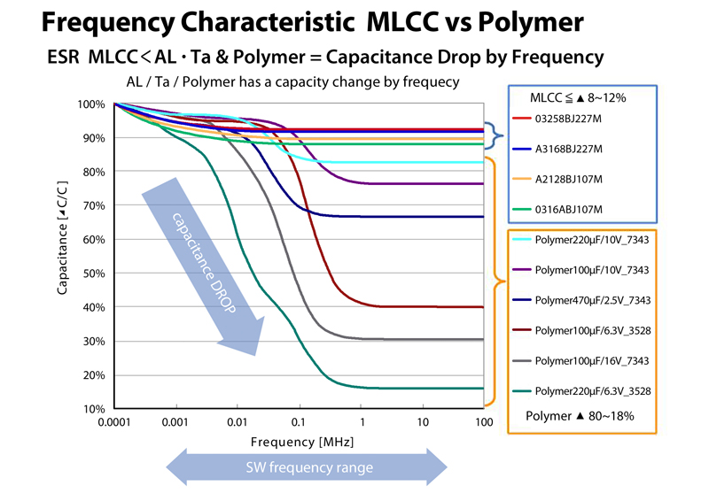
One of the more dramatic improvements provided by MLCCs occurs with the reduced change of capacitance over frequency. Figure 3 compares frequency characteristics of MLCCs and polymer designs. Over a frequency range of 100Hz to 100MHz, four MLCCs varied by only 8% to 12%, compared to an 18% to 80% change in six polymer devices.
Click image to enlarge
Figure 3. Frequency impact on the capacitance values of MLCCs compared with polymer capacitors
MLCC application examples
MLCCs offer improvements in performance over electrolytics that include both physical size and electrical advantages. Additionally, in some applications, comparable performance can be achieved with a lower capacitance (and even smaller) MLCC.
Output voltage stabilization
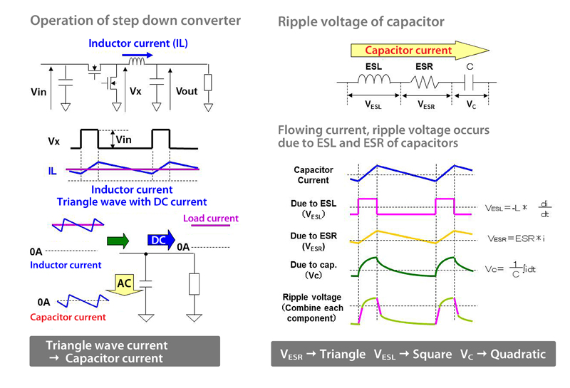
To achieve improved efficiency, today’s digital products are increasingly equipped with switching-type power supplies. These power supply circuits use combinations of high-value capacitors to smooth the output and ensure the stable operation of other circuitry within the end product. Figure 6 shows an example of using MLCCs to improve the waveforms in a step- down converter.
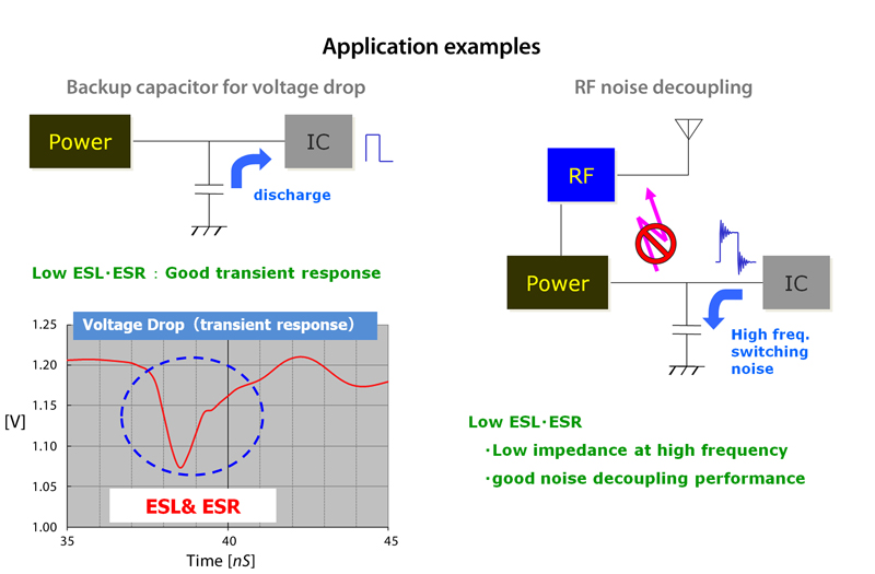
The important benefits of high-value MLCC technology in this application are the significant reduction in component size and the reduction in both ESR and ESL when compared with electrolytics. Figure 4 depicts low ESR and ESL of capacitors contribute to reduced ripple currents.
Click image to enlarge
Figure 4. Ripple voltage occurrence mechanism in a step-down converter due to ESR and ESL of capacitors
Noise filtering
At high frequencies, an MLCC can filter RF noise and minimize the disruptive impact of high frequency spikes on other circuitry. Figure 5 shows an example of this application. The MLCC’s better performance over a wider frequency range combined with low ESR and ESL make it well suited for this application.
Click image to enlarge
Figure 5. RF noise decoupling benefits of using MLCCs
Evolution and technology
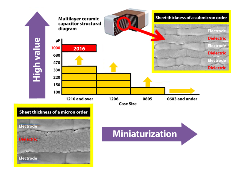
Figure 6 illustrates the evolution of mass-produced, high-capacitance MLCCs in various industry-standard packages. As is shown, the trend in MLCCs has been toward higher capacitance and shrinking form factors.
Click image to enlarge
Figure 6. The trend in MLCC technology toward smaller size and higher capacitance
Material science
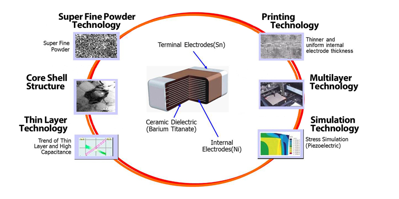
MLCCs require a variety of key technologies to achieve increasingly higher values. As shown in Figure 7, these technologies include:
• Super-fine powder technology
• Core-shell structure
• Thin layer technology
• Printing technology
• Multilayer technology
• Simulation technology
Click image to enlarge
Figure 7. Key technologies for MLCCs to achieve high capacitance values.
The core technology that enables the high-volume manufacturing of compact and high capacitance products is the ability to make both thin and uniform dielectrics. By controlling the thickness of dielectrics, TAIYO YUDEN currently has technology that exhibits insulation properties in regions less than one-micron thick.
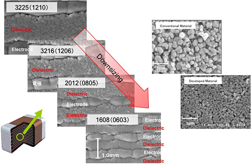
Refining and advancing the technology to manufacture thin and uniform sheets occurs by controlling the powder from the synthesis of the raw materials to dispersion, and the total process of laminating, firing and then finishing these sheets. Figure 8 shows the decreases in dielectric and electrode that result from increasing finer powder and uniform-sheet technology.
Click image to enlarge
Figure 8. TAIYO YUDEN’S core technology results in more compact and higher capacitance MLCC products.
Producing MLCCs with values well above 100µF requires extensive research in laboratory and manufacturing technology. This knowledge is essential for achieving accurate laminations as well as for overcoming the challenges of firing an increasing numbers of layers.
Acoustic noise suppression
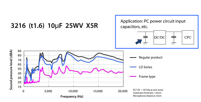
The ferroelectric ceramic materials commonly used in high capacitance-type MLCCs can result in mechanical distortions when an electric field is applied. With an AC voltage, the capacitor vibrates and transmits this vibration to the substrate creating an audible sound. In response to this issue, acoustic noise-suppression dielectric materials have been developed that are used in commercialized capacitors to reduce the acoustic noise.
These acoustic noise-reducing products also provide a small capacitance decrease due to the DC bias voltage, making them ideal for use in the power circuits of notebook PCs. For example, in measurements using a voltage waveform across an actual circuit, it was confirmed that there is a sound pressure reduction effect compared with products with regular X5R characteristics, as shown in Figure 9.
Click image to enlarge
Figure 9. MLCCs with acoustic noise-reduction measures to reduce sound pressure levels.Soft Termination
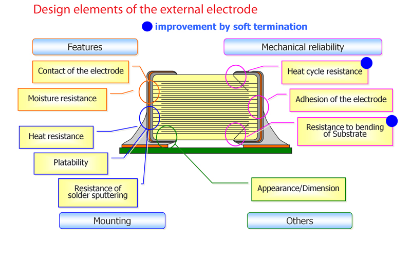
Figure 10 shows the design elements of the external electrodes for MLCCs, including soft-termination aspects. A soft termination provides heat cycle resistance and resistance to substrate bending.
Click image to enlarge
Figure 10. MLCCs’ soft-termination provides heat-cycle resistance and resistance to substrate bending
Looking forward
Due to the advantages provided by multilayer ceramic capacitors, MLCC devices have proven their ability to replace polymer capacitors in many consumer, industrial and automotive applications. Increasingly higher-value MLCCs are poised to bolster this trend.