Figure 1: Optocoupler Construction
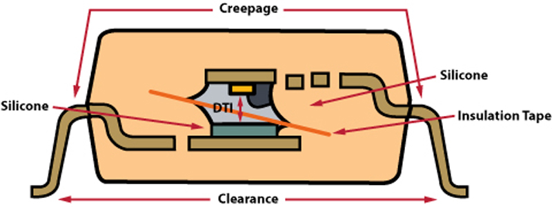
Isolation components such as optocouplers that are used in applications that have user safety issues as a key aspect must not fail under continuous high-working-voltage bias conditions. Safety hazards exist and human life is at risk when such insulation fails and the high voltages come in contact with the user. To prevent such occurrences, continuous working voltage ratings and test methodologies are regulated by international component standards and equipment safety standards. To provide designer confidence, isolator products must be certified to ensure that they meet the required insulation levels for the desired safety ratings. Equipment manufacturers, to meet the system safety ratings will often use isolators that are certified to meet recognized standards in order to ensure safety and compliance to regulations. These isolation requirements are met through mechanical constructional guidelines and component safety standards. Optocouplers are a prime example of components that are currently regulated by component level safety standards. An example of an optocoupler standard is VDE0884 which was subsequently replaced by DIN/EN 60747-5-2/ DIN/EN 60747-5-5. This standard was developed to address all of the specific safety aspects of optocoupler technology. One of the key achievements of this standard is the implementation of 100% manufacturing test methodology. This methodology is able to reliably prove the long-term high-voltage endurance of every manufactured optocoupler. In recent years, alternative isolators using different coupling technologies, e.g. magnetic and capacitive isolators, have been introduced to the market. These alternative isolators are typically built using ultra thin (10μm-20μm) insulation layers, while optocouplers have insulation thicknesses of 80μm to 1000μm. The thinner insulation barrier in the alternative isolators experiences higher electric-field stress for the same working voltage, and thus may be more prone to failure than the optocouplers. Aside from the mechanical differences, optocouplers and alternative isolators use different insulation materials. Optocouplers typically use homogenous polyimide/silicone while alternative isolators use either spin coat polyimide or silicon dioxide (SiO2). And since there are no existing standards for these alternative isolators, as a compromise, some test houses offer certified compliance to the optocoupler standard DIN/EN 60747-5-2. Test bodies have only issued certification of BASIC insulation, which implies a partial compliance but not a full certification. That is because the quality and characteristics of thin-film polyimide and CMOS insulation with respect to safe insulation application is not well understood. Additionally, there is the question of whether the high-voltage aging mechanisms for the optocoupler and alternative isolators are similar. VDE0884-10 is a draft standard that has its roots in the VDE0884 optocoupler standard. This standard relies on the partial discharge principle to predict safe, continuous high-voltage lifetimes. Since the drafting of VDE0884-10, it has been proven that partial discharge is not the principle aging mechanism of alternative isolators. There are other aging mechanisms active at lower stress voltage levels for these alternative isolators. The practice of using optocoupler test methods for alternative isolators has raised concerns and questions. This article is intended to provide experimental test data and analysis to address such concerns. Insulation Construction Optocoupler, magnetic isolator and capacitive isolator have the following differences: (1) insulation material, (2) mechanical construction, (3) insulation thickness and (4) dielectric breakdown strengths. Optocouplers, such as the Avago HCPL-316J for example, use thick insulation material composed of polyimide tape and silicone on both sides of the optical path (see Fig 1). The distance through insulation (DTI) is a minimum of 400 μm.
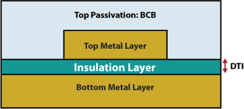
Magnetic isolators are built on monolithic CMOS ICs with a thin layer of spin-on polyimide as insulation (see fig 2). Its DTI can be as low as 17 μm. Similarly, capacitive isolators on CMOS ICs use a thin layer of SiO2 as insulation with min DTI of 8μm. Recently, some manufacturers have increased the DTI to 16μm to handle a higher insulation voltage. However, there are limitations for DTI to increase further due to: The effects of DTI on signal coupling efficiency The process of depositing thick insulation on CMOS ICs is expensive and poses reliability concerns. As a result, the electric field stress in alternative isolators is at least 20X larger than that of an optocoupler for the same working voltage. This difference is significant, suggesting that a new aging mechanism and defect screening method must be defined and developed. Optocoupler Safety Standard and Test Method for Continuous Working Voltage International safety standard IEC 60747-5-5 covers electrical characteristics and test methods for photo couplers or optocouplers only and not for magnetic and capacitive digital isolators. It was officially released in 2007. The previous versions of the standard, IEC 60747-5-1/2/3, which cover optoelectronic devices including optocouplers, will be withdrawn in 2012. European standard DIN/EN 60747-5-2 adopted IEC 60747-5-2 and will be phasing out and withdrawn in 2014. It will be replaced by newly released DIN/EN 60747-5-5 based on IEC 60747-5-5. Both IEC 60747-5-5 and DIN/EN 60747-5-2 use the partial-discharge method to test the homogenous quality of solid insulation. In this test, voltages up to 1.875 times the rated working voltage are applied between input and output of the device for 1s. A discharge of less than 5pC (picocoulombs) must be satisfied in order to pass this test. This test does not only guarantee the high quality of insulation, but it also effectively eliminates devices with any manufacturing defects, which would result in reduced lifetimes and safety hazards. This is one of the key tests that position the standard to be widely recognized by equipment safety standards, including: IEC 61800 - Standard for Industrial Motor Drives etc. IEC 60950 - Standard for IT and Communication Equipments IEC 60601 - Standard for Medical Equipments; and IEC 61010 - Test and Measurement Equipments The aging mechanism for alternative isolators varies with insulation material. Magnetic isolators employ spin-on polyimide as an insulation layer. Manufacturers use a thermodynamic model to project the device lifetime. Capacitive isolators employ SiO2 as insulation material; hence a TDDB (Time Dependant Dielectric Breakdown) model is used for lifetime prediction.
Table 1 summarizes the aging model/life prediction method and certification used to determine continuous working voltage of various isolation technologies. It is notable that alternative isolators use a prediction model that is different from the test method. Partial Discharge, Continuous Working Voltage and Life Time Prediction A simple experiment can be used to verify the correlation between partial discharge capability and continuous working voltage. Samples from different technologies, including optocoupler, magnetic and capacitive isolators in SOIC packages with 8mm creepage and clearance were selected. Since solid insulation is capable of 200Vrms/1mm, a test voltage of 1.6kVrms is selected for all devices to accelerate the test time. Before starting the lifetime stress test, all isolators were subjected to partial discharge (at 3kVrms, 1.875 times of 1.6kVrms per IEC/EN60747-5-5, VDE0884-10 and EN60747-5-2). The test result shows that all devices passed with a discharge of less than 5pC. This indicates that the insulation is good for 1.6kVrms in accordance to the standard.
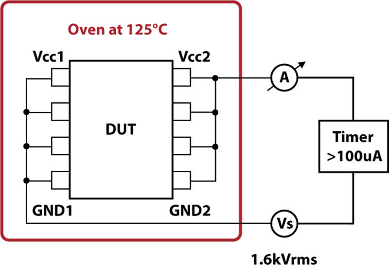
The setup of life time stress test is shown in Figure 3. Five units each of optocouplers, magnetic and capacitive isolators are placed together in an air circulating oven at 125oC. Test voltage of 1.6kVrms, at 60Hz AC voltage is applied continuously. The leakage current is constantly measured. An alarm sounds when the current meter detects more than 100μA leak. When a breakdown scenario occurs, the test is halted and all devices under test (DUTs) are bench measured for leakage current for fault identification.
The final test result revealed that the magnetic isolator and capacitive isolator break down after 12hrs and 21hrs respectively. The test was continued for the optocoupler, which did not fail for up to 4000hrs, wherein the test was halted. The optocoupler did not fail any current leakage test during and after the test. The partial discharge, life test result is summarized in Table 2 together with the projected life time predicted by respective manufacturers. Optocouplers have demonstrated good consistency and agreement between partial discharge test capability and actual life time stress performance. It was a surprise that the insulation of both magnetic and capacitive isolators broke down after a very short period of time, which was far shorter than the prediction of partial discharge, as well as the manufacturer's own prediction. Similar life test has been repeated several time and results are consistent. In proving a safe continuous working voltage rating, this test result reaffirms that partial discharge is the relevant test method for optocouplers. However, the partial discharge test is a totally unsuitable test method for alternative isolators. In particular, it indicates an overrated and subsequently dangerous continuous operating high voltage. Manufacturers of alternative isolators should supplement the partial discharge test with additional high-voltage lifetime modeling techniques. These modeling techniques are based on type test data generated during accelerated conditions. However, this lifetime prediction method poses some amount of risk because: Assumption of failure rates should not be done for safety applications; There are large differences between accelerated conditions and actual end-use conditions. This translates into a possibility of large errors in modeling methods; and There is no continuous monitoring of manufacturing variations as well as 100% production testing to screen out manufacturing defects, e.g. pin holes, particles, voids and etc. Conclusion International safety standard IEC 60747-5-5 and European standard DIN/EN 60747-5-2 (based on earlier revision of IEC 60747-5-5) specifies that this test method is suitable and applicable for photo couplers or optocouplers only, and not on magnetic and capacitive digital isolators. The standards take isolation construction, insulation material, aging mechanism and defect screening test into consideration. It is well established and proven effective through millions of optocouplers in use in the field application for decades. Laboratory result of high voltage life test correlates well with the partial discharge test prediction for optocoupler. Alternative isolators based on monolithic IC fabrication processes, e.g. magnetic and capacitive isolators, typically are built using thin layers of insulation. Such isolators experience considerably higher electric field stress for the same working voltage when compared to that of optocouplers. Consequently, alternative isolators suffer from multitude of additional aging mechanisms which are active at relatively low continuous working voltages. The standards, which are based on partial discharge principle, are not suitable in providing reliable continuous working voltage ratings for alternative isolators. Supplementary high-voltage aging modeling data offered by some manufactures represents a poor substitute for an independent safety standard. It rarely represents a suitable level of due diligence for reinforced applications. Laboratory test results clearly show the risk of alternative isolators using optocoupler standards. An in-depth study of such technologies and their limitations should be carried out before wide market adoption. Use of such alternative isolator devices in safety related application presents safety risk to equipment users and requires design engineer's careful examination, thorough qualification and certification for regulatory compliance and long-term reliability of the end equipment. www.avagotech.com


